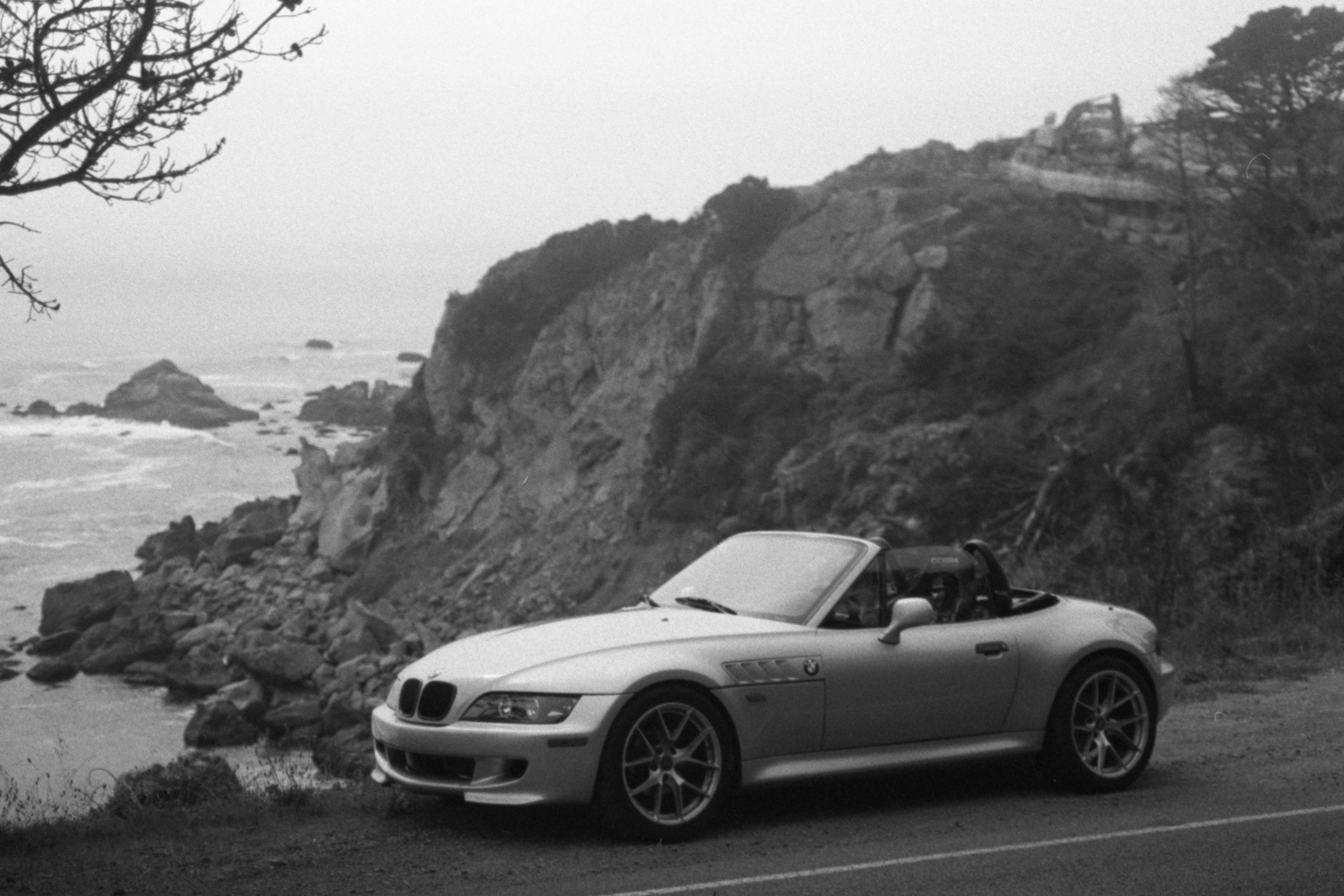
BMW Z3 Track Car Build
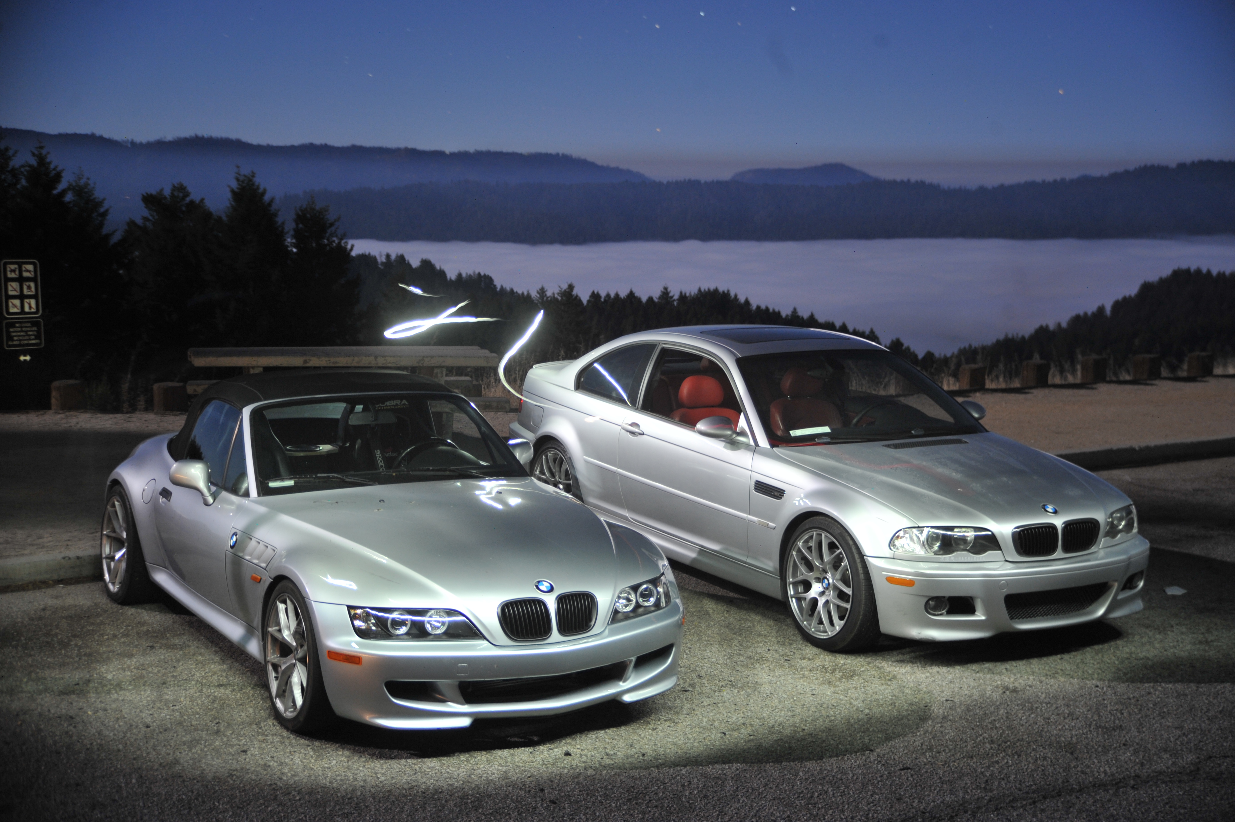
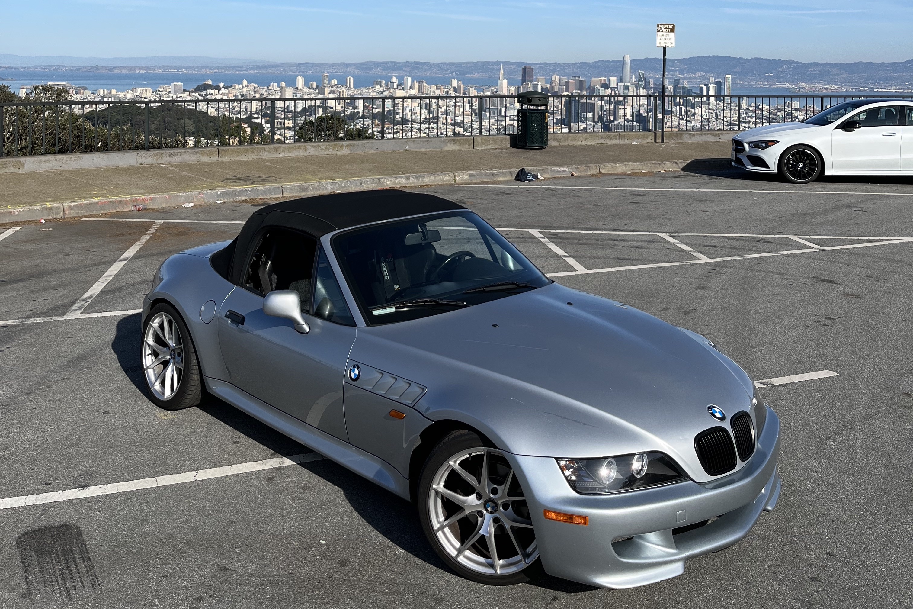
Starting with a 1999 BMW Z3 2.3 convertible, I did all of the modifications to convert it into an S54-powered track car.
Project History
2019:
I purchased the car for $4500 from an elderly woman in Stockton, California. It had 137,000 miles on the chassis and a 2.3L M52TU engine paired with a Getrag 5 speed manual transmission. The first modifications made to the car were a new set of wheels, 18x8.5 in the front and 18x9.5 in the rear.
2020:
After being sent home from university during the pandemic, I addressed some critical issues in the rear of the Z3's chassis, known to arise after prolonged spirited driving. The primary design flaw present in the rear of the chassis is due to the older, E30 style, rear semi-trailing arm suspension design being used in a vehicle with more power and more grip. The rubber bushings holding the rear subframe to the chassis wear and allow for rotational movement along the axis of the driveshaft, in turn putting strain on the single differential mount, held to the trunk floor with several spot welds and presumably hopes and dreams. After enough fatigue from heavy acceleration and braking, the welds fatigue, fracture, and the entire rear differential mount rips free from the trunk floor, leading to a miserable clunk.
There are several solutions, however, knowing my intentions for this car were exclusively spirited driving and track time, I chose to design a weld-in solution that would be strong enough to withstand all that would be demanded from the car. This consists of a new chromoly steel differential mount, made from a 4"x4" 10-gauge steel square structural member, with 1"x2" and 0.75"x1" chromoly reinforcements triangulated in the direction of highest load on acceleration. The design was verified using SolidWorks Simulation, and the new differential mount was fabricated outside the car before being welded to the chassis and trunk floor using plug welded gussets. The installation was completed using etching primer, seam sealer, and two component automotive paint, sealing the retrofit from the elements.
Polyurethane bushings throughout the rear eliminated the issue of subframe deflection, and new Feal 441 coilovers gave the car a new outlook on cornering and stability. After these modifications I promptly ran out of cash and returned to university in Colorado.
2021-23:
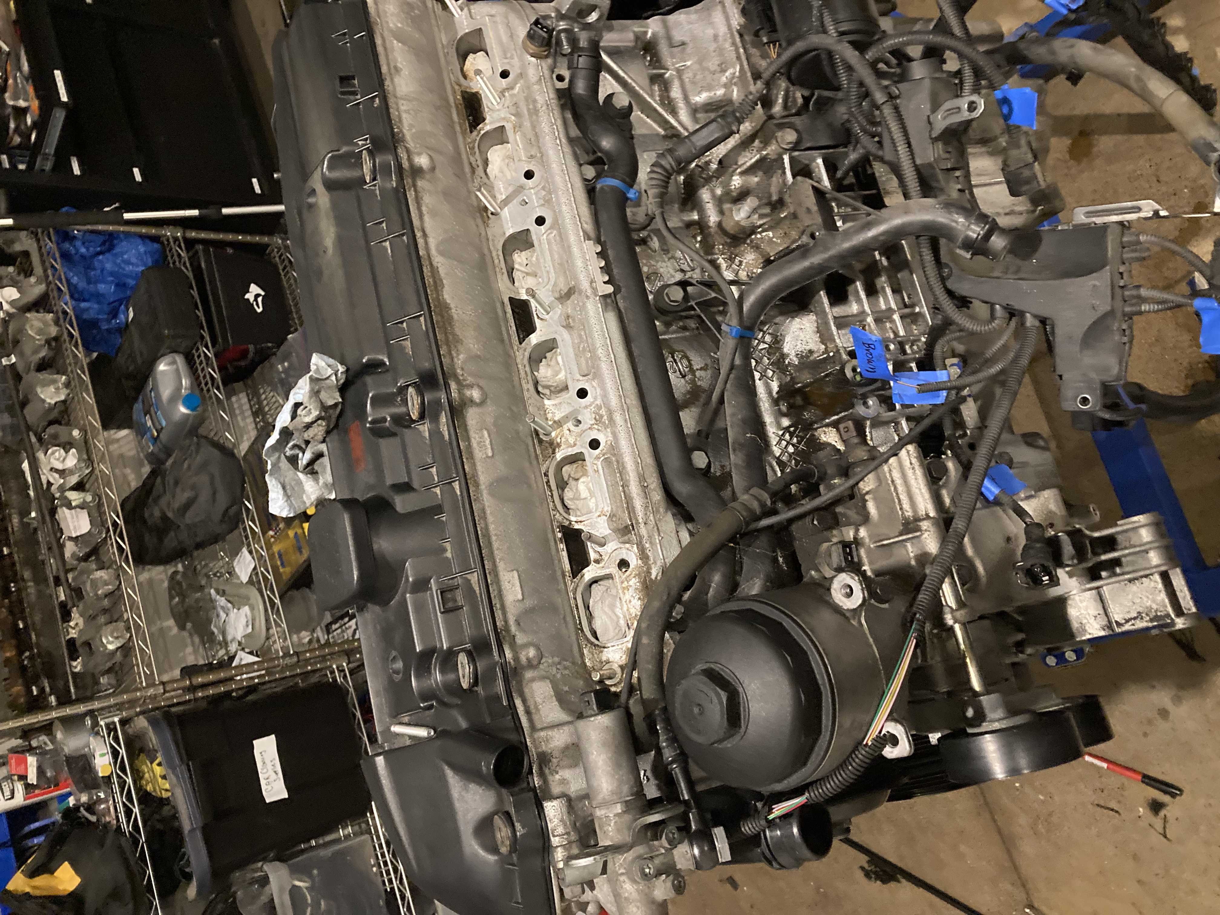
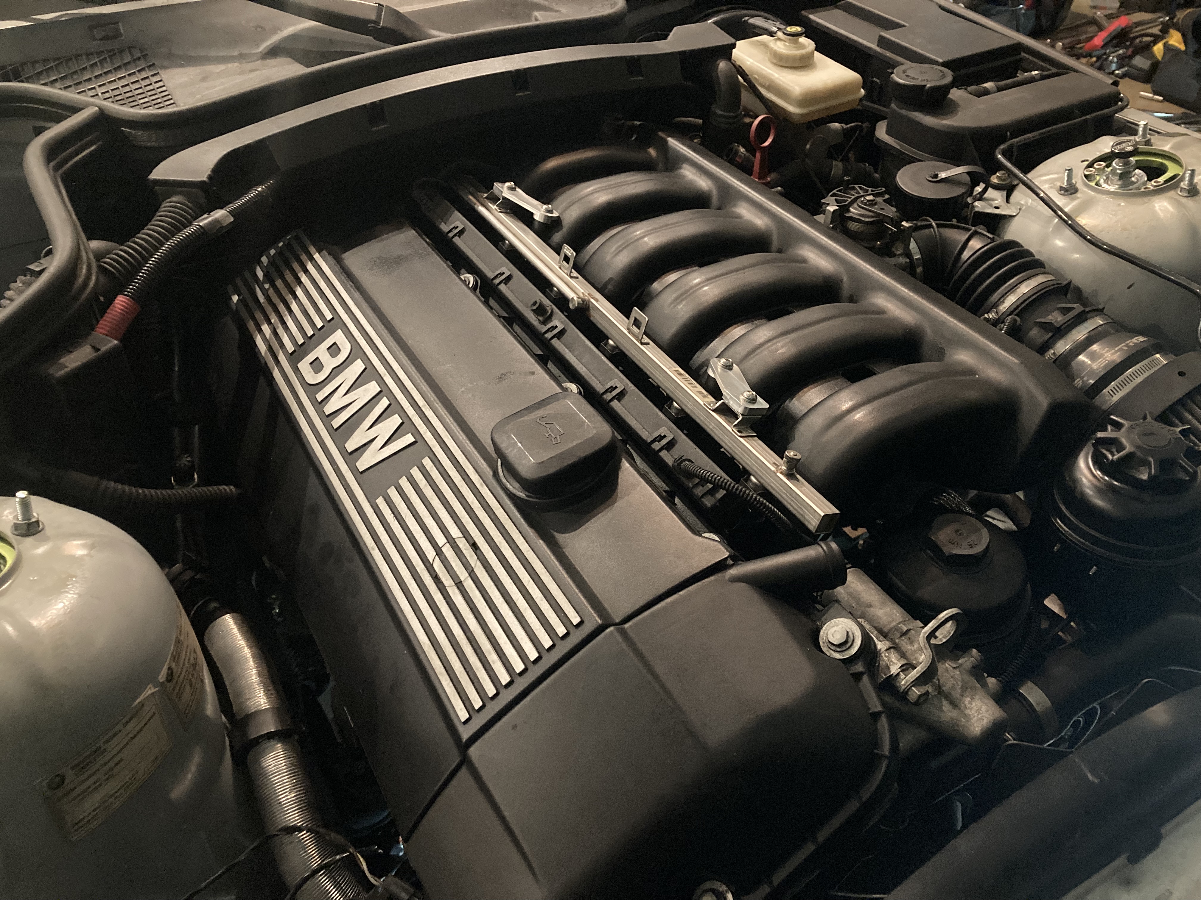
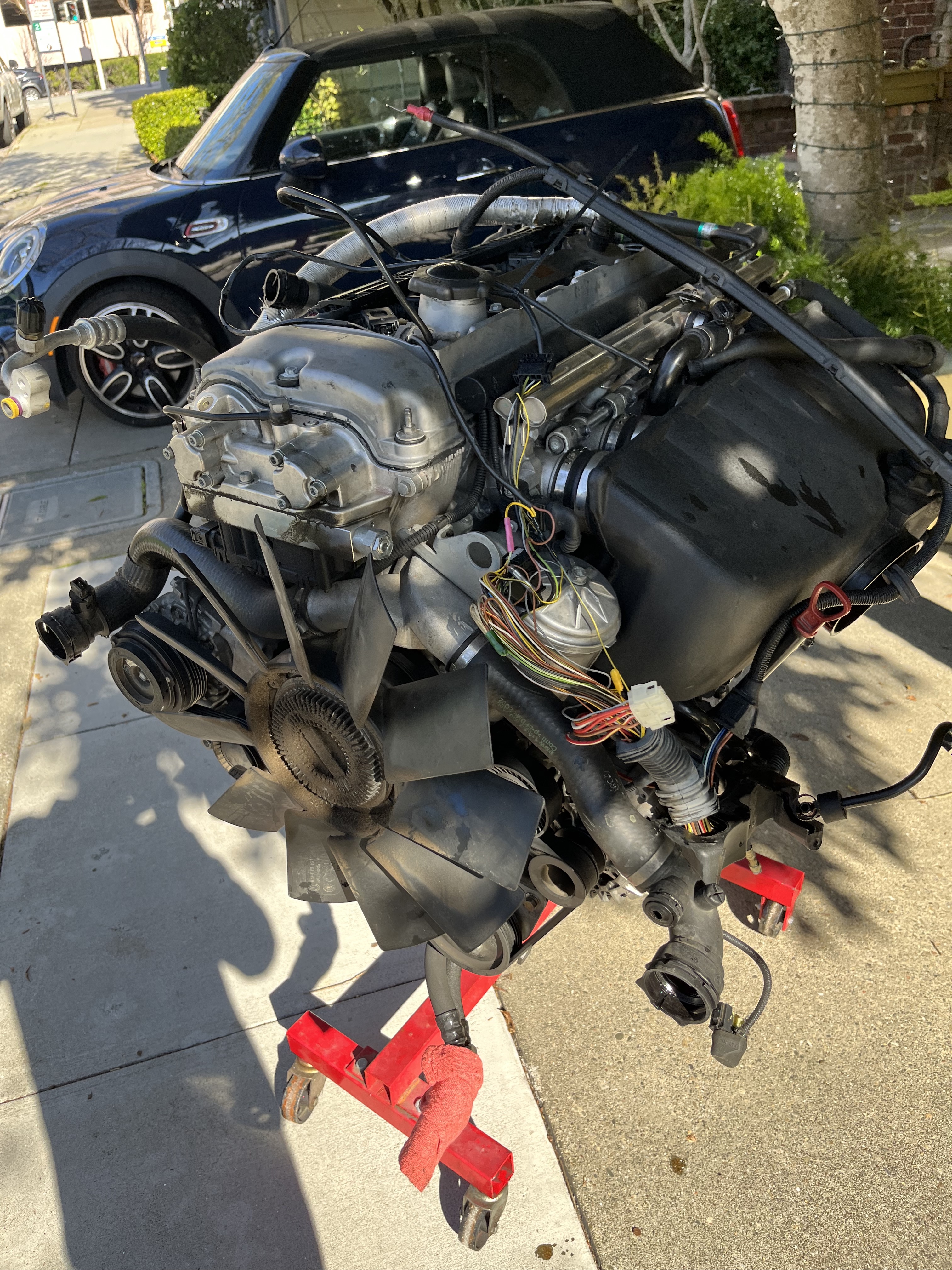
I returned for the summer of 2022 with renewed motivation, this time to abandon the original drivetrain in pursuit of more power. Being financially limited as a broke university student, I chose the route of a junkyard M54B30 from a 2002 pre-facelift 330i that I was able to buy for $300. A few hundred more on refurbishment supplies later, the new engine was re-sealed and mounted in the car with a new clutch but the same Getrag 5 speed transmission. What followed was a series of increasingly inconsequential decisions about how to adapt certain systems of the vehicle from a chassis designed for an M52TU to an M54 motor.
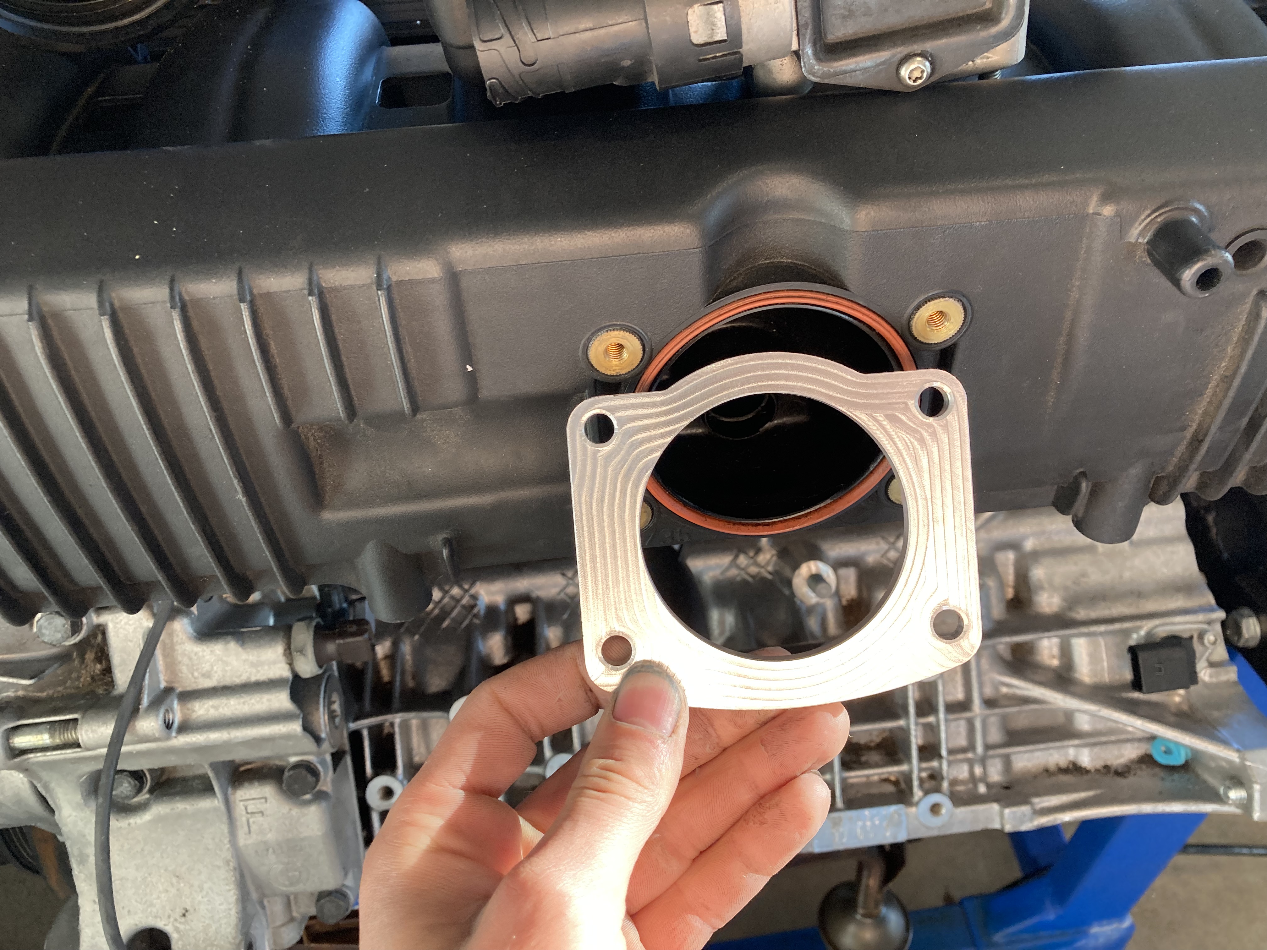
To squeeze more power out of the M54B30, a motor designed with reliability in mind, I swapped the restrictive intake manifold for one from an M50 motor out of a pre-facelift E36, and used less restrictive exhaust headers. This manifold combination is a classic bolt-on solution for increasing flow through the motor, and while it is common to see a small decrease in torque, it is acompanied by a 20-30HP gain when tuned appropriatley. To further facilitate an increase in flow through the restrictive M54 head, I port matched the intake side of the head using a carbide burr to exactly match the M50 manifold's runners.
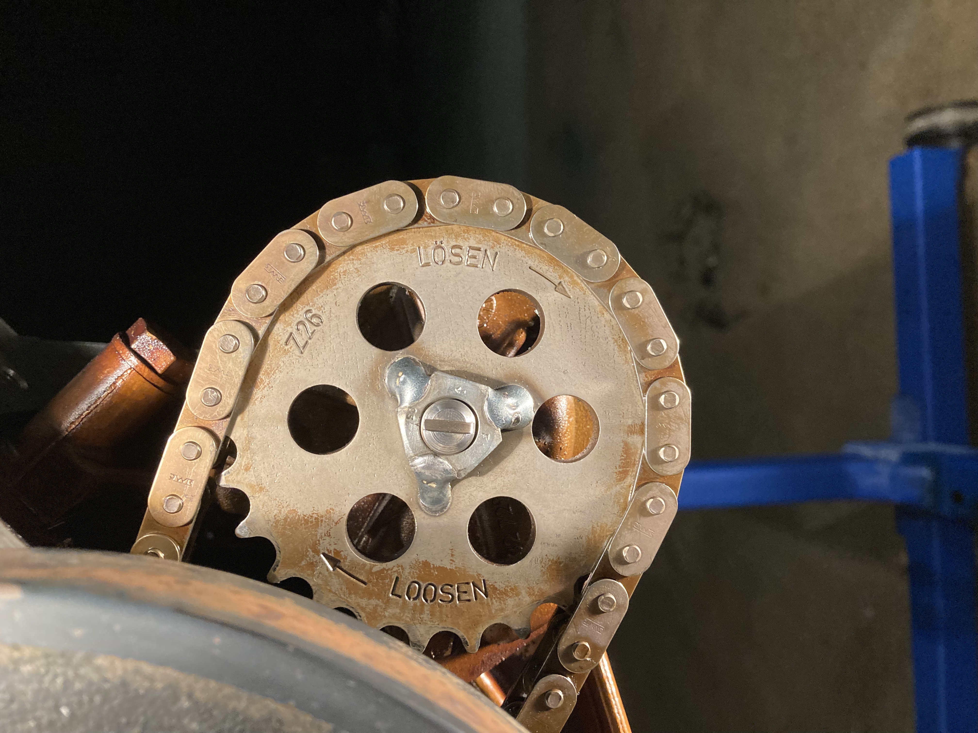
A common issue with M54 motors, specifically when they are operated at or near redline consistently, is that the oil pump nut can back off of the shaft. Common fixes include adding a safety wire to the oil pump nut, replacing the entire pump with one not suceptible to this issue, or in my case, tack welding the nut.
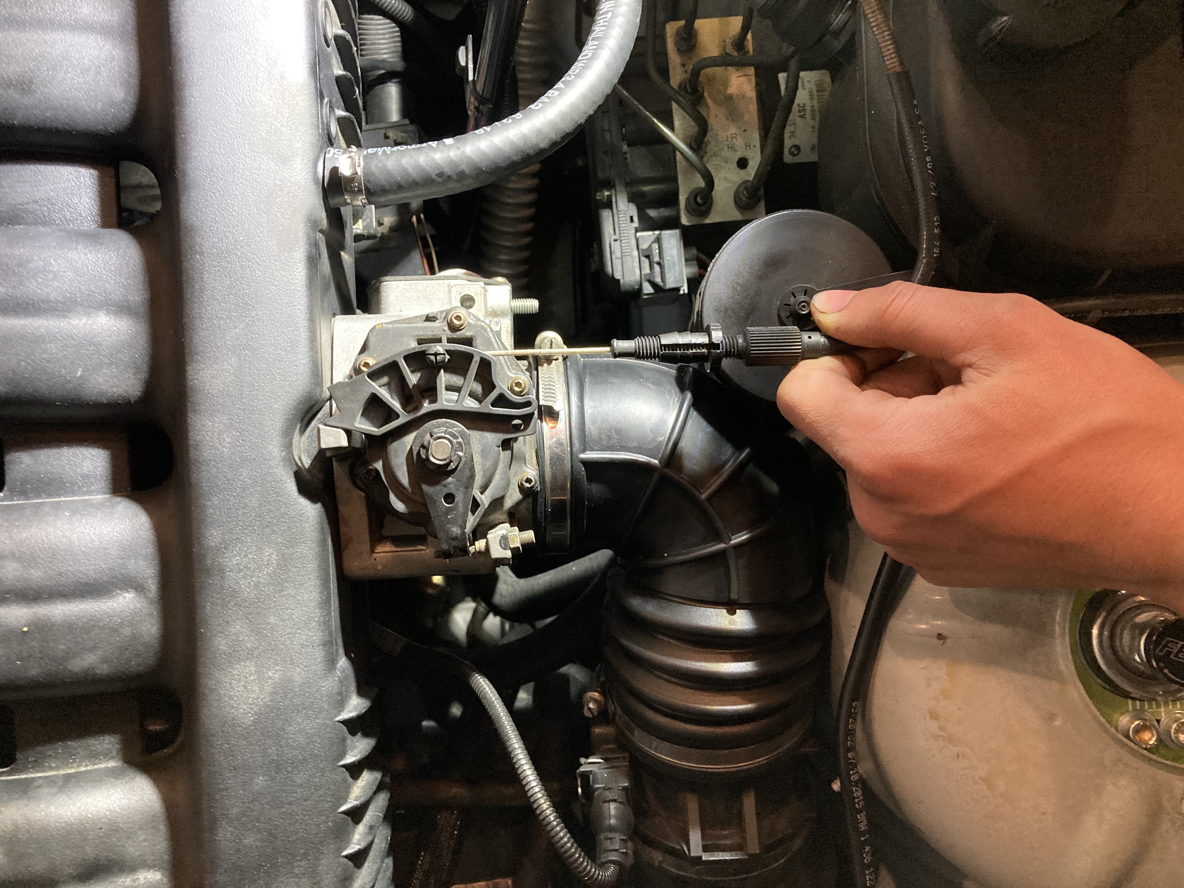
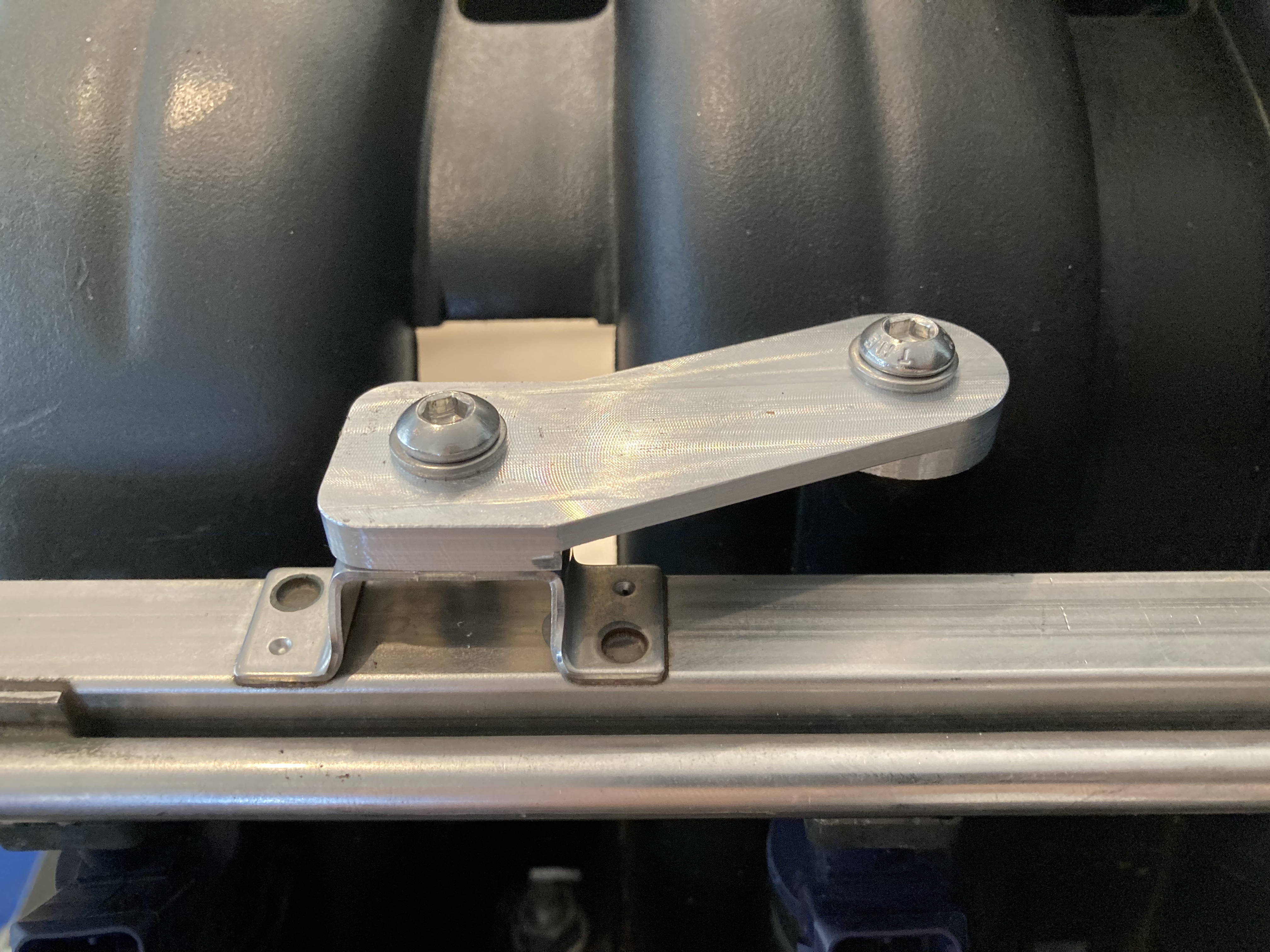
I learned, in excruciating detail, the subtle differences between both platforms, and became increasingly certain that the Z3 was just made from scraps laying around the BMW factory in Spartanburg. The throttle is an example emblematic of these nuanced discrepancies; the Z3 chassis was designed in a time of cable throttle, when a physical steel cable would connect the pedal directly to the throttle body, while the M54 hails from a time of drive by wire throttle, where both the electronically actuated throttle body and potentiometer on the pedal connect to the DME. Similar adaptations and modifications were strewn throughout the drivetrain, and made up most of the work, and most of the opportunities for custom bracketry and engineering solutions.
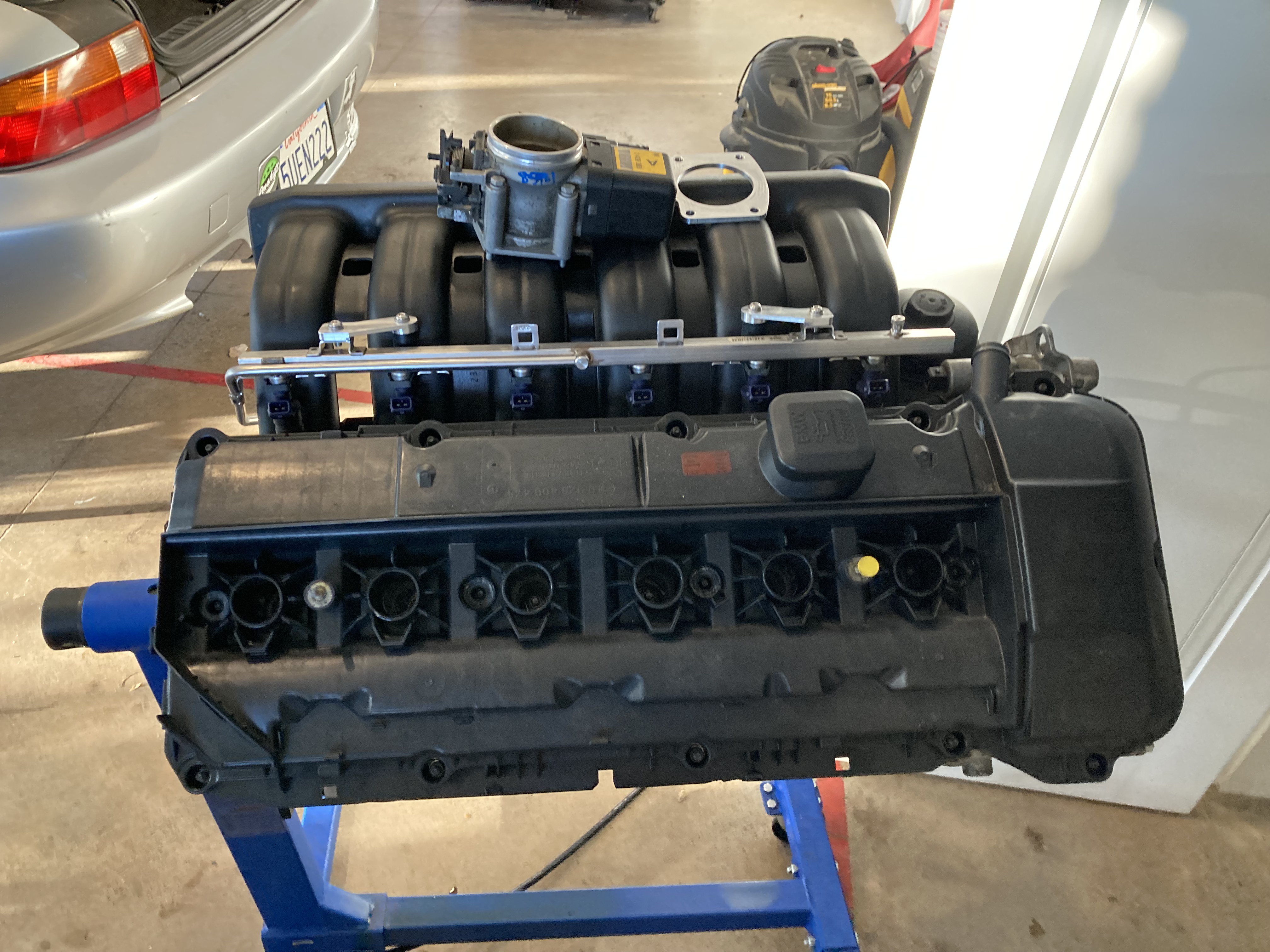
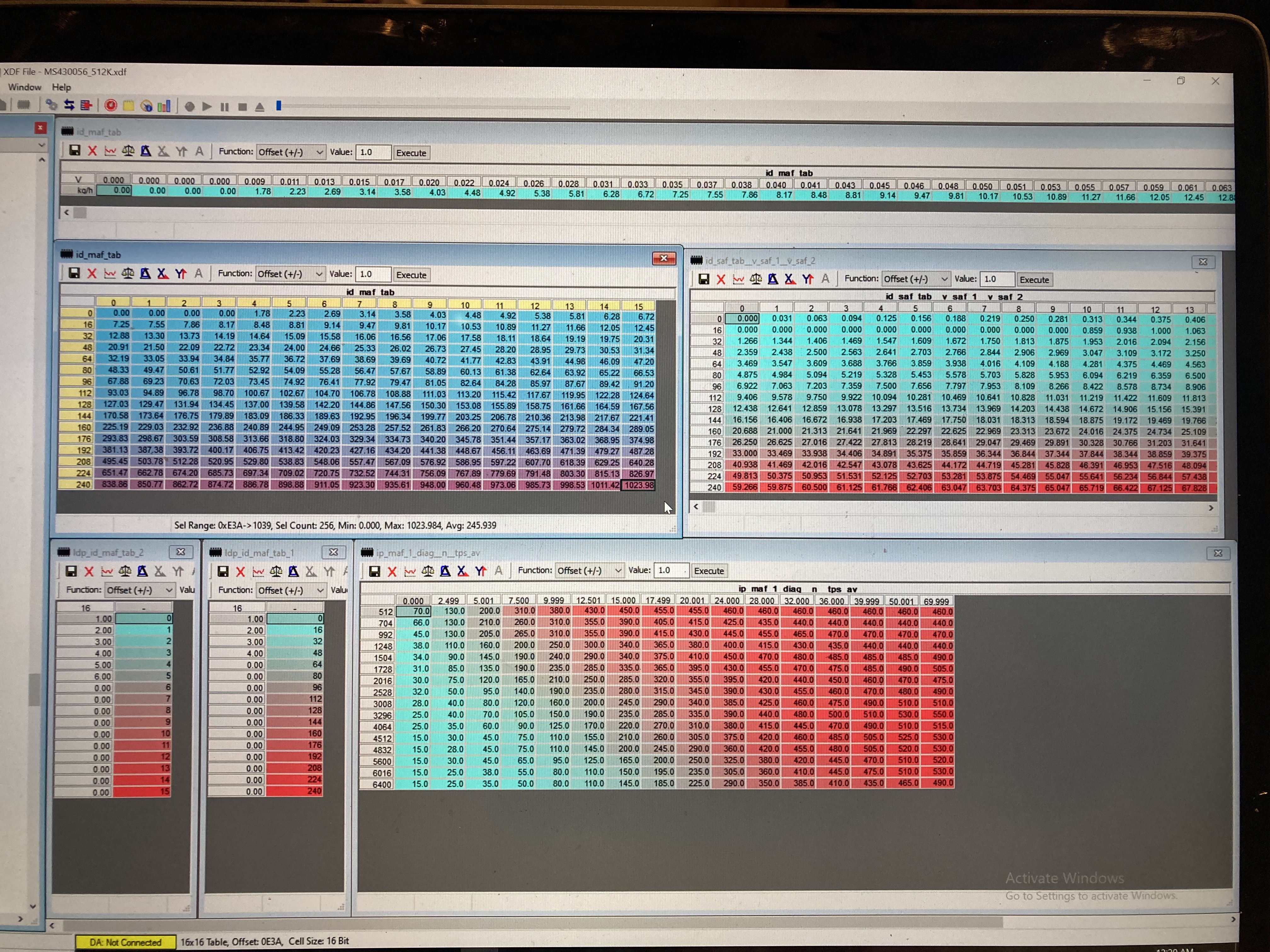
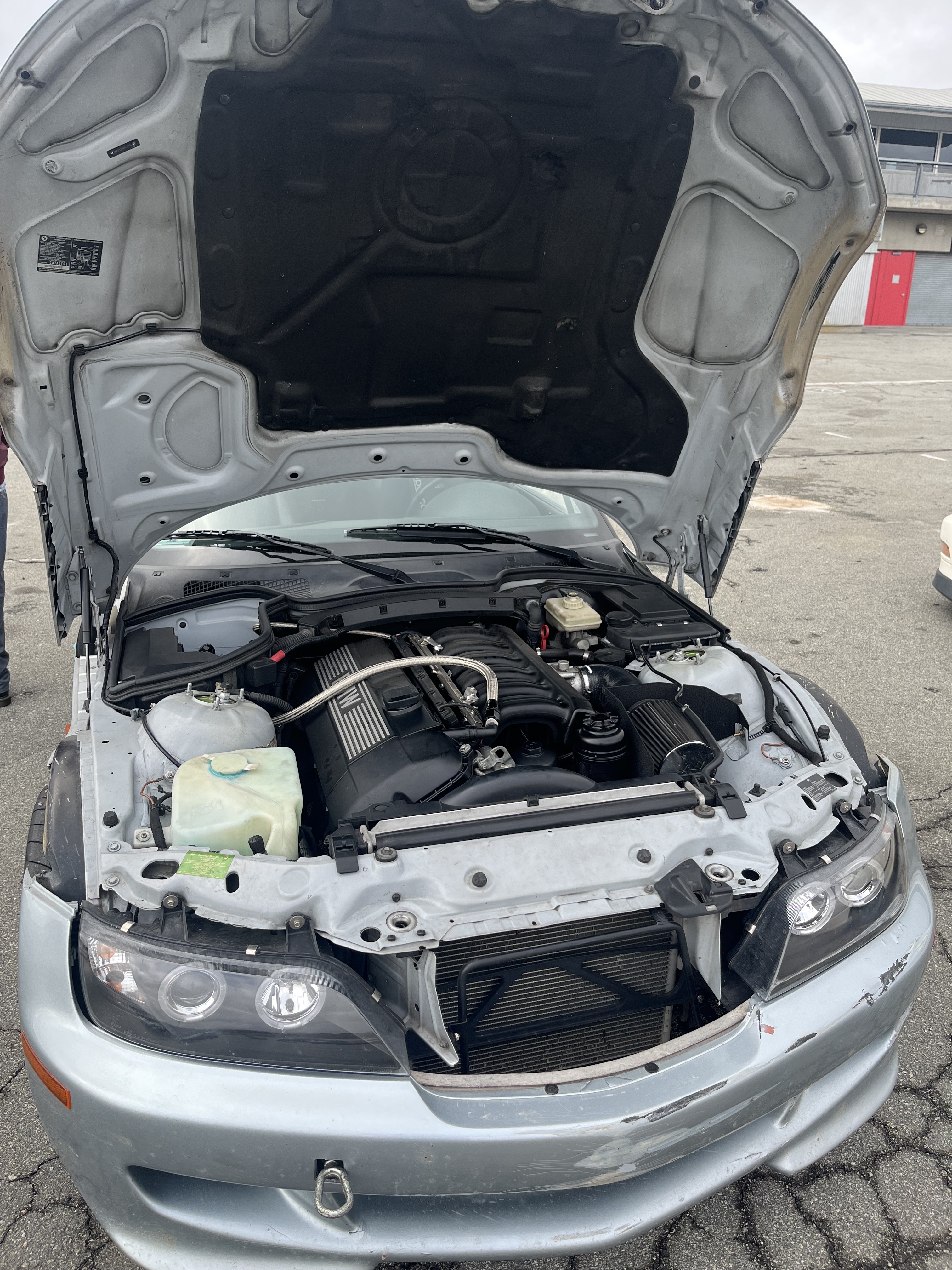
By the end of the summer, I had a fully functional Z3 3.0 equivalent, complete with a custom intake system, exhaust manifold, catch can, and tuned to run the better-flowing M50 intake manifold. Theoretical power was between 230-250 HP, however this powerplant would meet its demise before I could test that theory.
2024:
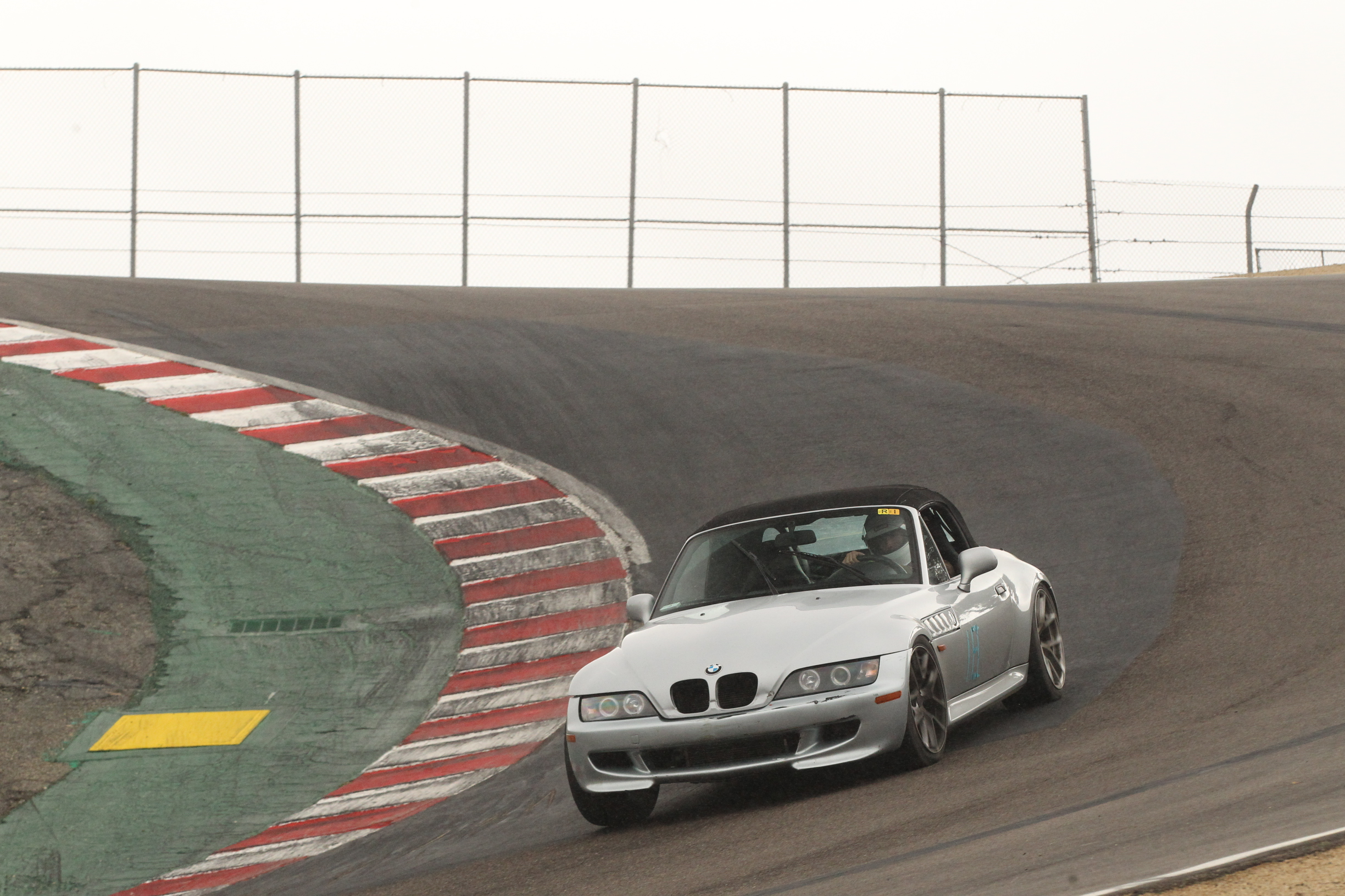
My M54B30 finally met its limit during the twilight laps of a long day of sessions at Laguna Seca. I had seen flickers of red on the dash during hard cornering as the oil sloshed across my unbaffled oil pan, but I had dismissed it as a non-issue due to the brevity of the warning light. As I was lifting off while passing the sound booth I heard some unfortunate noises, presumably coming from my crankcase, and made the decision to just keep on it and send it back to the pits. Not even 400 feet later, the noises intensified and concluded in a large clunk that locked my rear wheels mid-way up the hill to the corkscrew. I quickly put in the clutch and coasted off track. The motor had seized completely, but stayed intact, no oil and rod pieces out on track, no reprimanding from the track manager, but a total loss for my junkyard B30. As I towed the car home, I promised myself to not let it rot in the garage, and that I would be back for revenge next year.
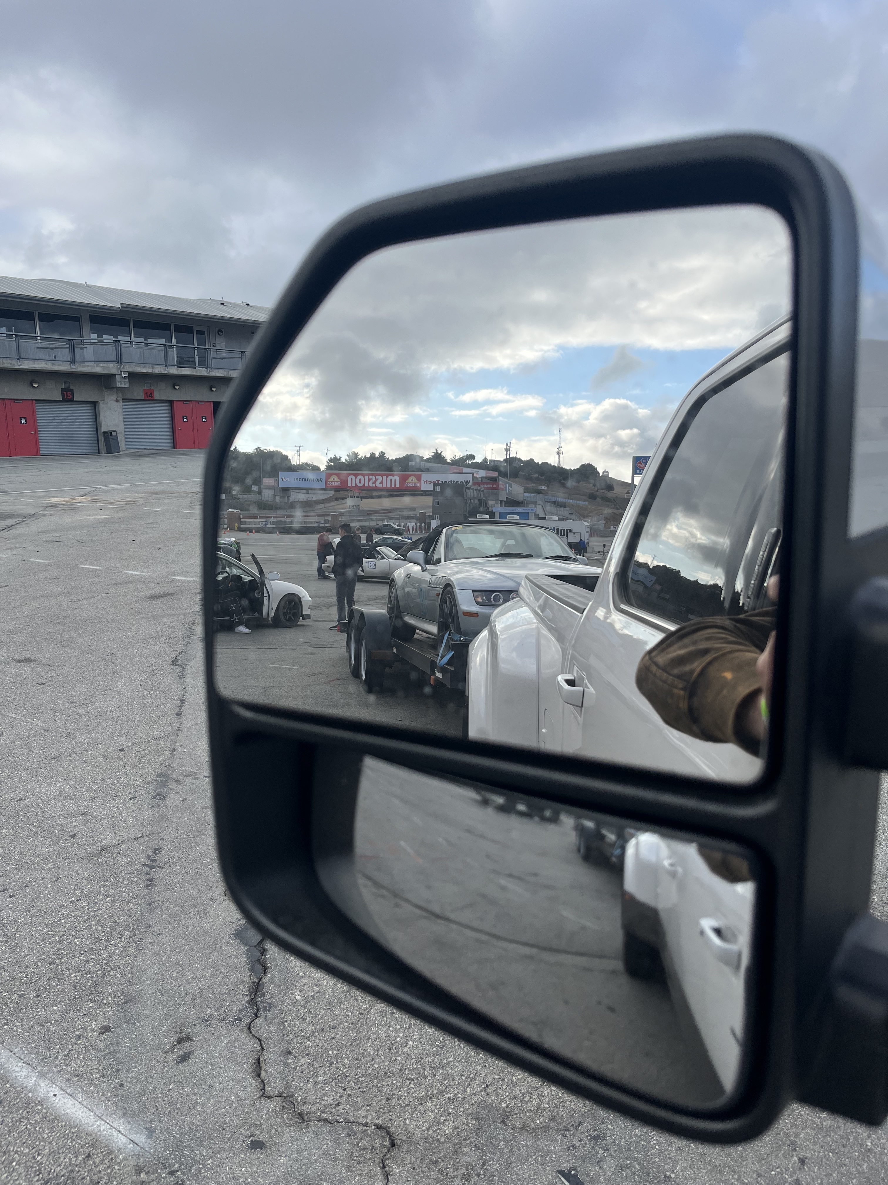
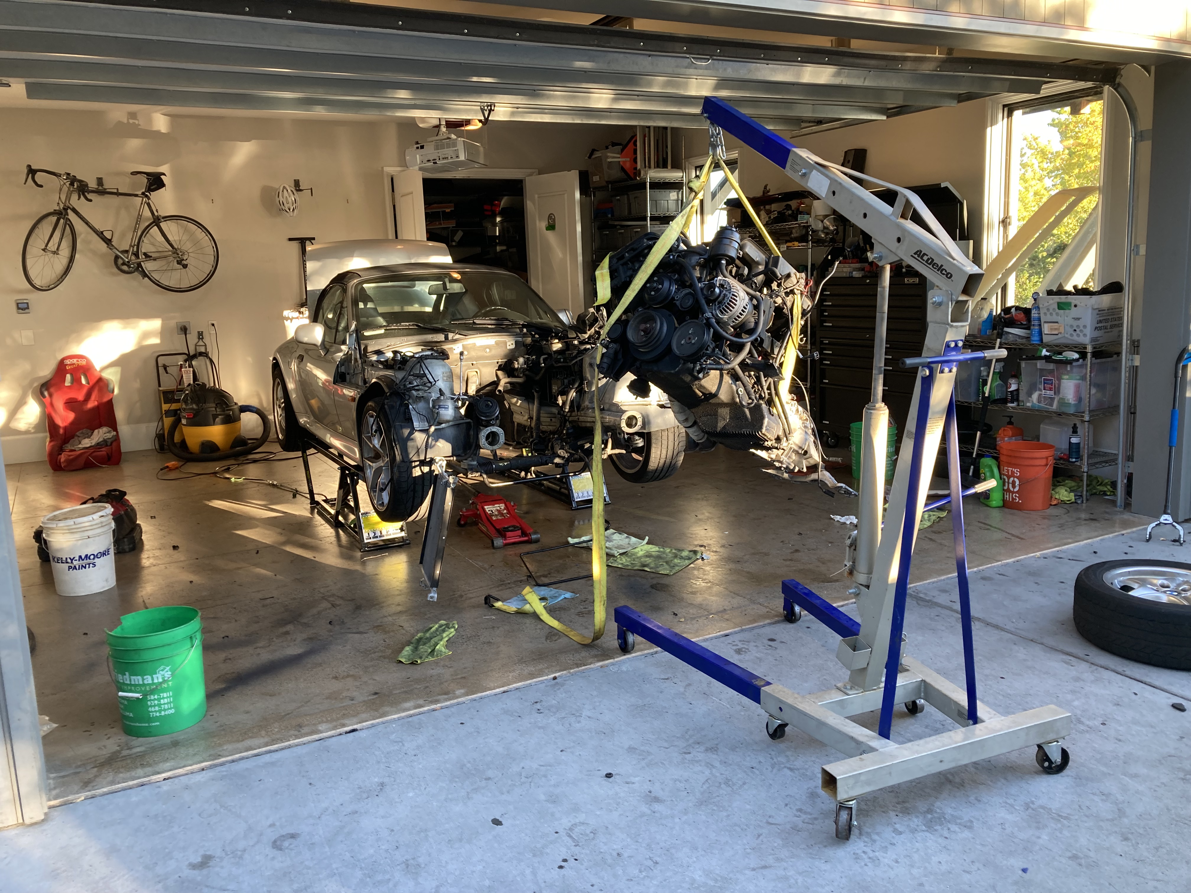
2025:
I started plotting my revenge while sitting in the tow truck at Laguna, but needed some cash to make it happen. So I worked overtime, 12 hour days, one extra per week, for two months until I had enough to make it happen. Step one was to find the replacement motor, I was done messing with junkyard engines, and for a naturally aspirated track build Z3, there seemed to be a clear right choice. I flew back to the bay and drove two hours north with Ethan to Clearlake, a sleepy town northeast of Santa Rosa, to pull my new motor. The motor in question, an S54B32, my M54's older, sportier cousin. 100 extra HP, individual throttle bodies, and most importantly an oiling system designed for track driving, with a baffled pan and two oil pickups. The donor car, a 2004 BMW M3, convertible, SMG, dove leather, silver paint, "S54 shipping container spec" according to Ethan. The owner of the car, a charismatic, middle aged high school teacher, had ambitions of EV swapping the car. I had no idea why someone would want to discard the most integral part of the E46M3's excellent driving experience in favor of a cold, torqey EV drivetrain, but to each their own. One long day of toil in the low January sun later, we were driving home with a new-to-me motor.
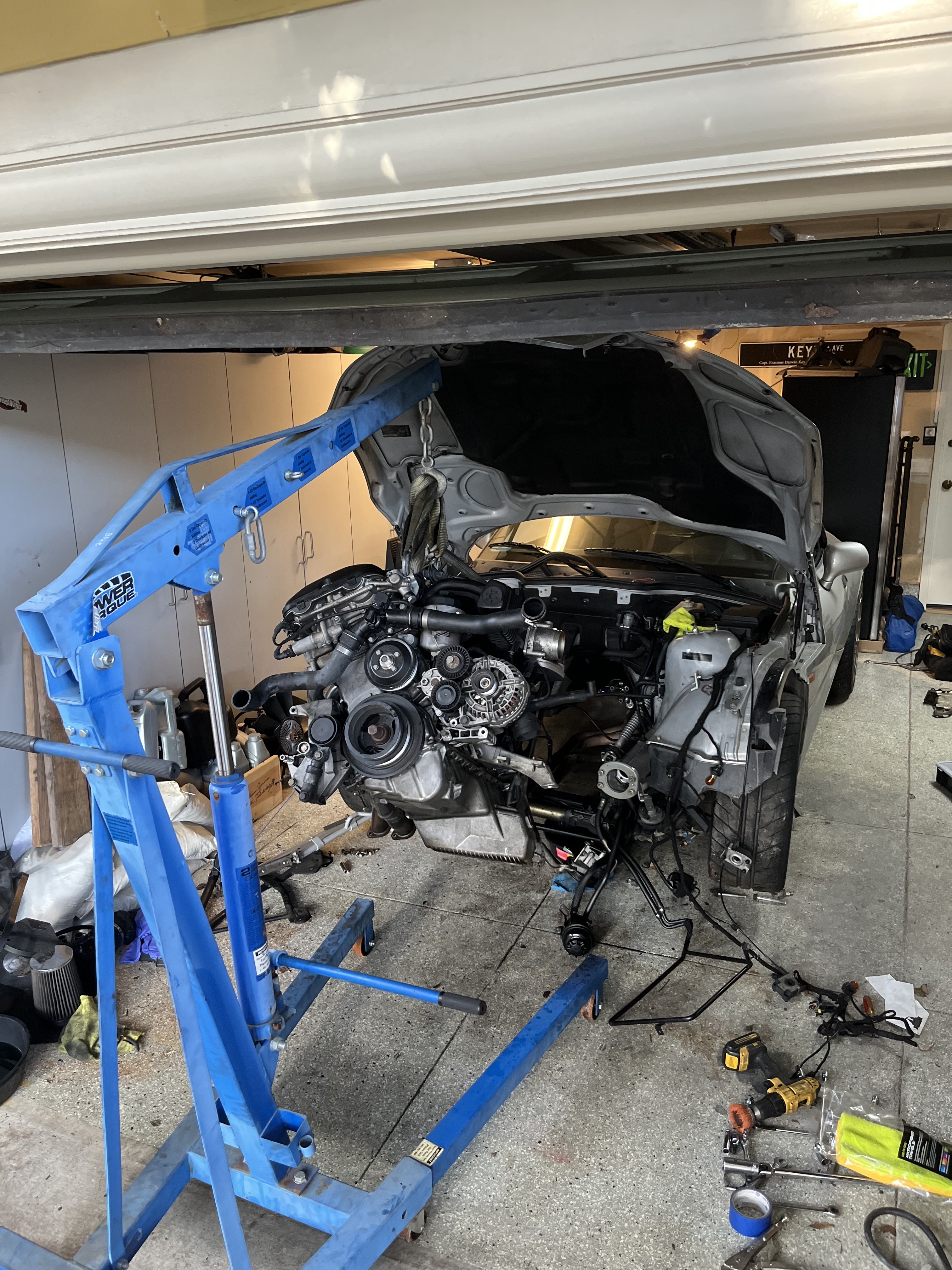
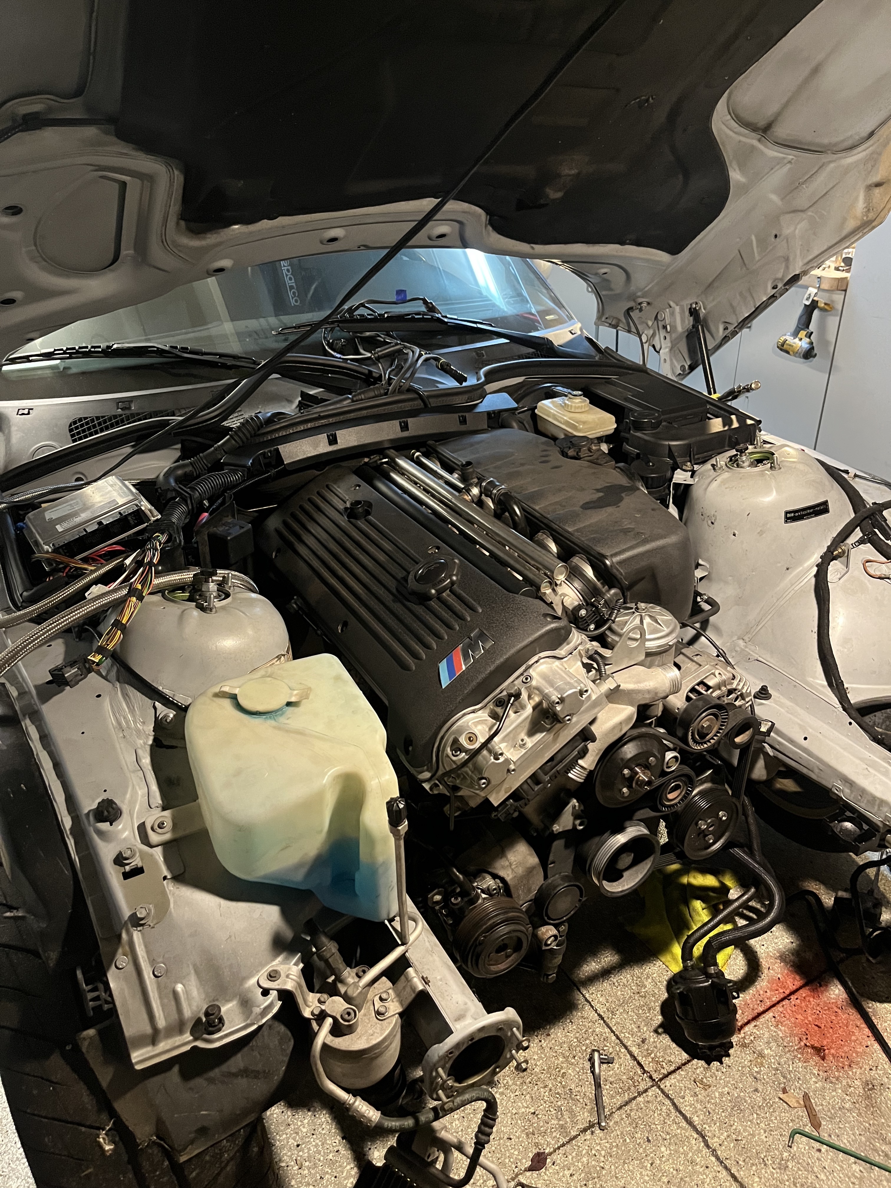
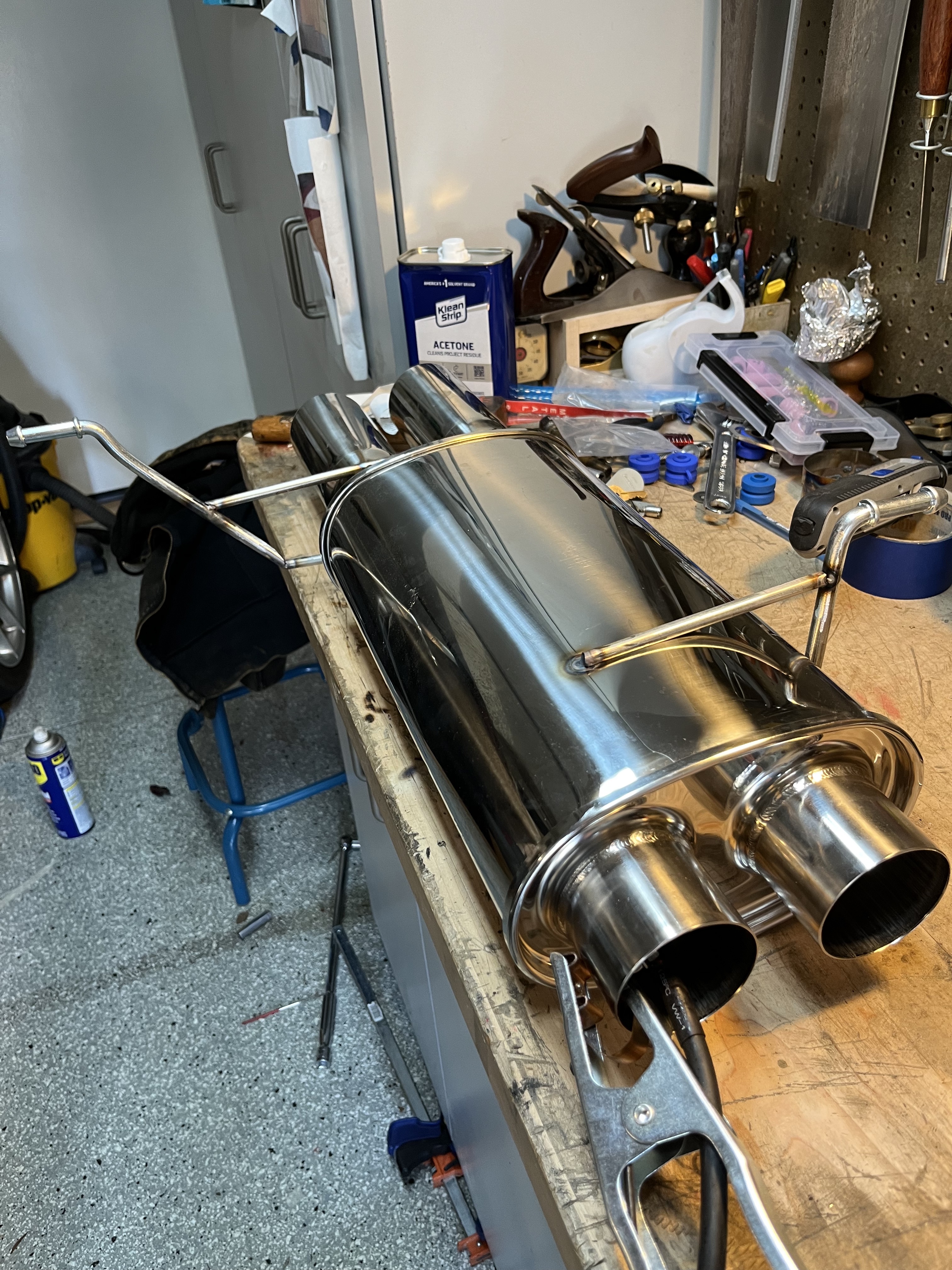
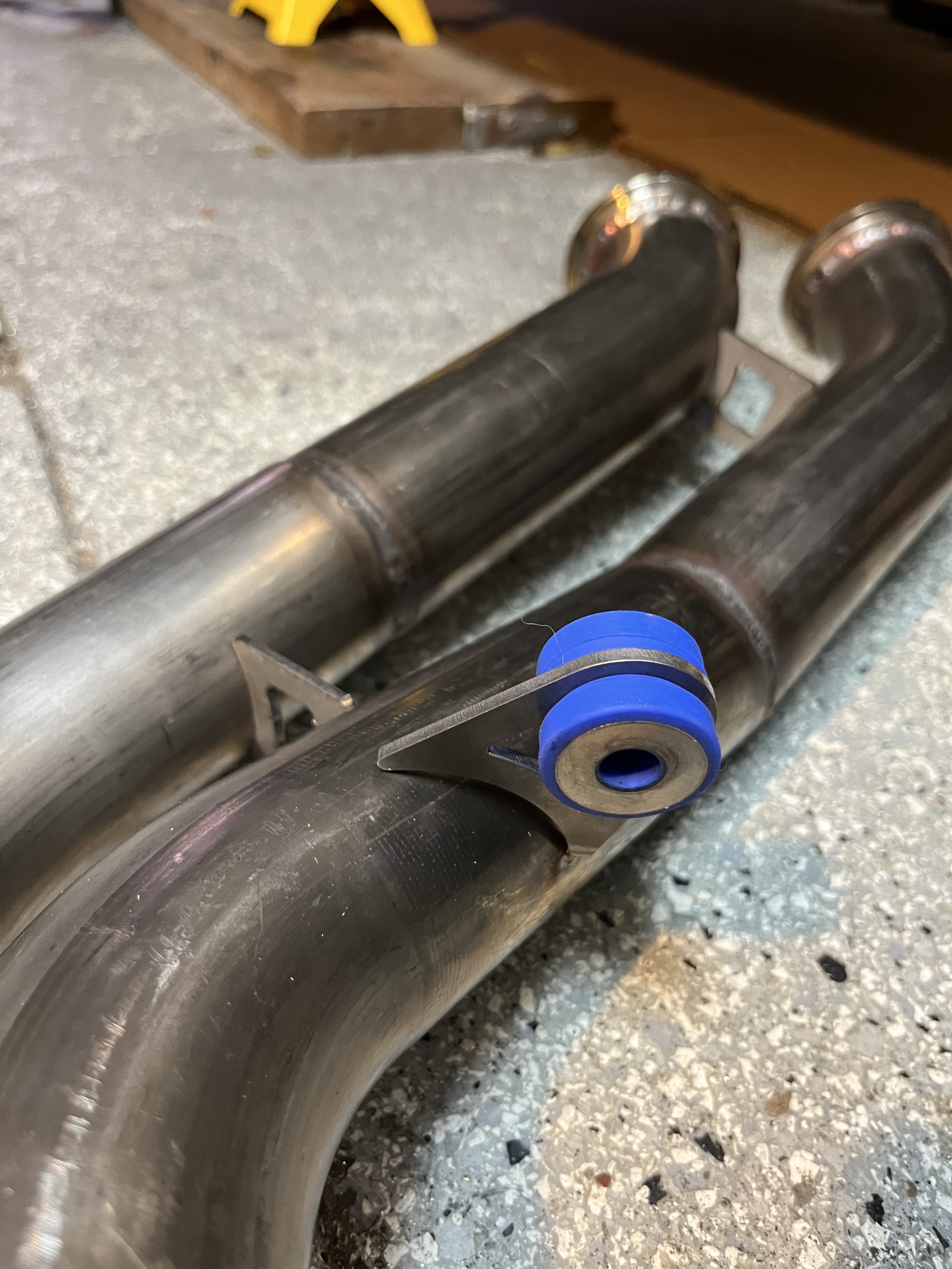
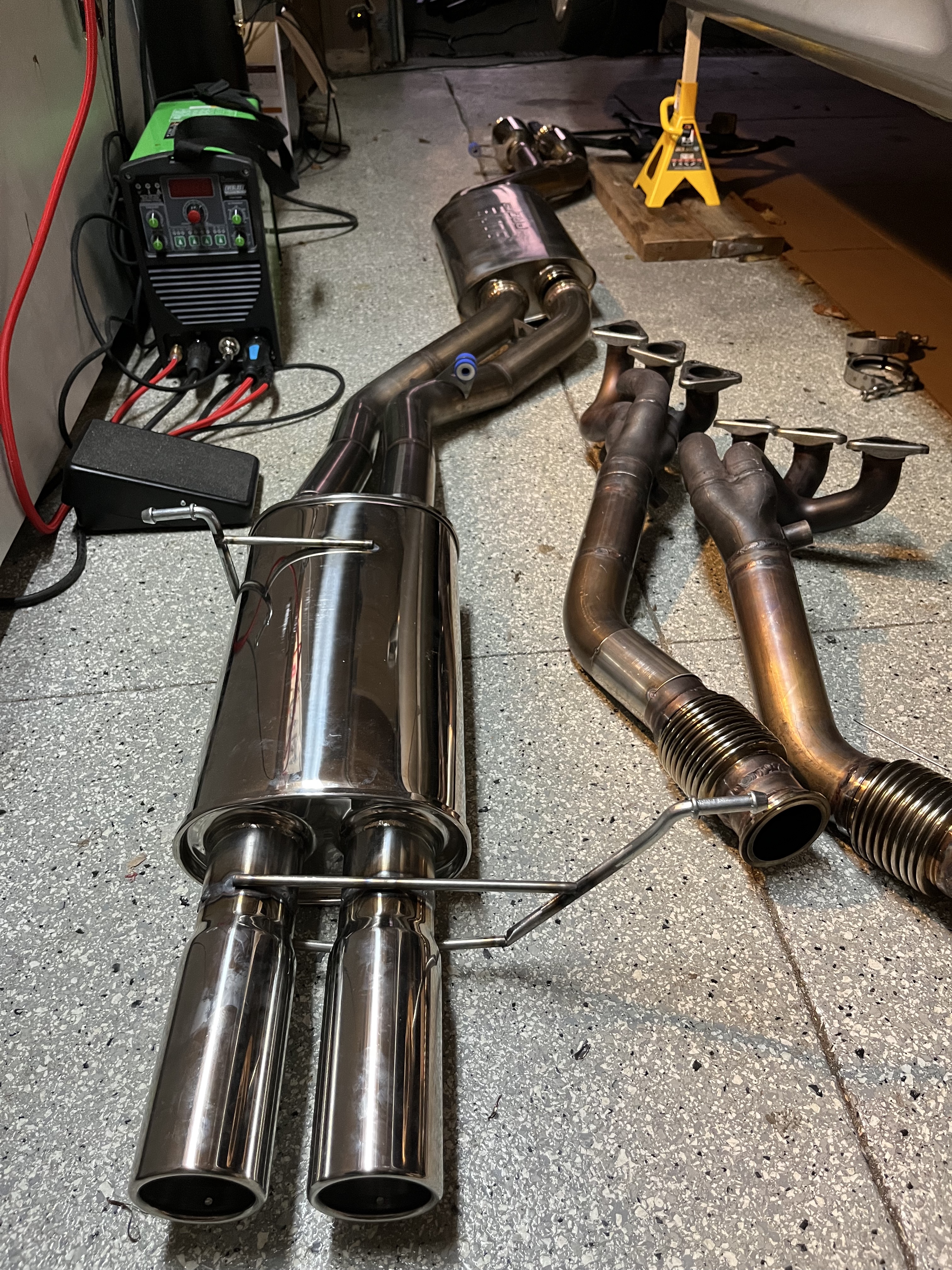
I returned to work on the car every month, mounting the drivetrain, adapting systems, similar to when I did the original swap, but with much more experience and understanding. Original S54 Z3 parts, made for the 2001 and 2002 model year Z3M model, are rare and expensive. So, to reduce the cost of the swap I chose to adapt parts such as those for the cooling system to work with my M54B30 chassis. I built a custom 304 stainless steel exhaust, constructed from 2 individual 2.5-inch tubes, two mufflers, resonators, and vband clamps. designed and fabricated mounts for an oil cooler, built an intake system, and simplified the wiring.
One of the most interesting parts of the process was modifying the original DME program file to allow me to run the motor with minimal safety systems. I disabled several systems within the program to simplify the operation of the vehicle: - Secondary air injection system, a pump designed to slow the warming of the catalytic converters by injecting cool air into the exhaust during startup - Secondary O2 sensors - EWS Immobilizer system
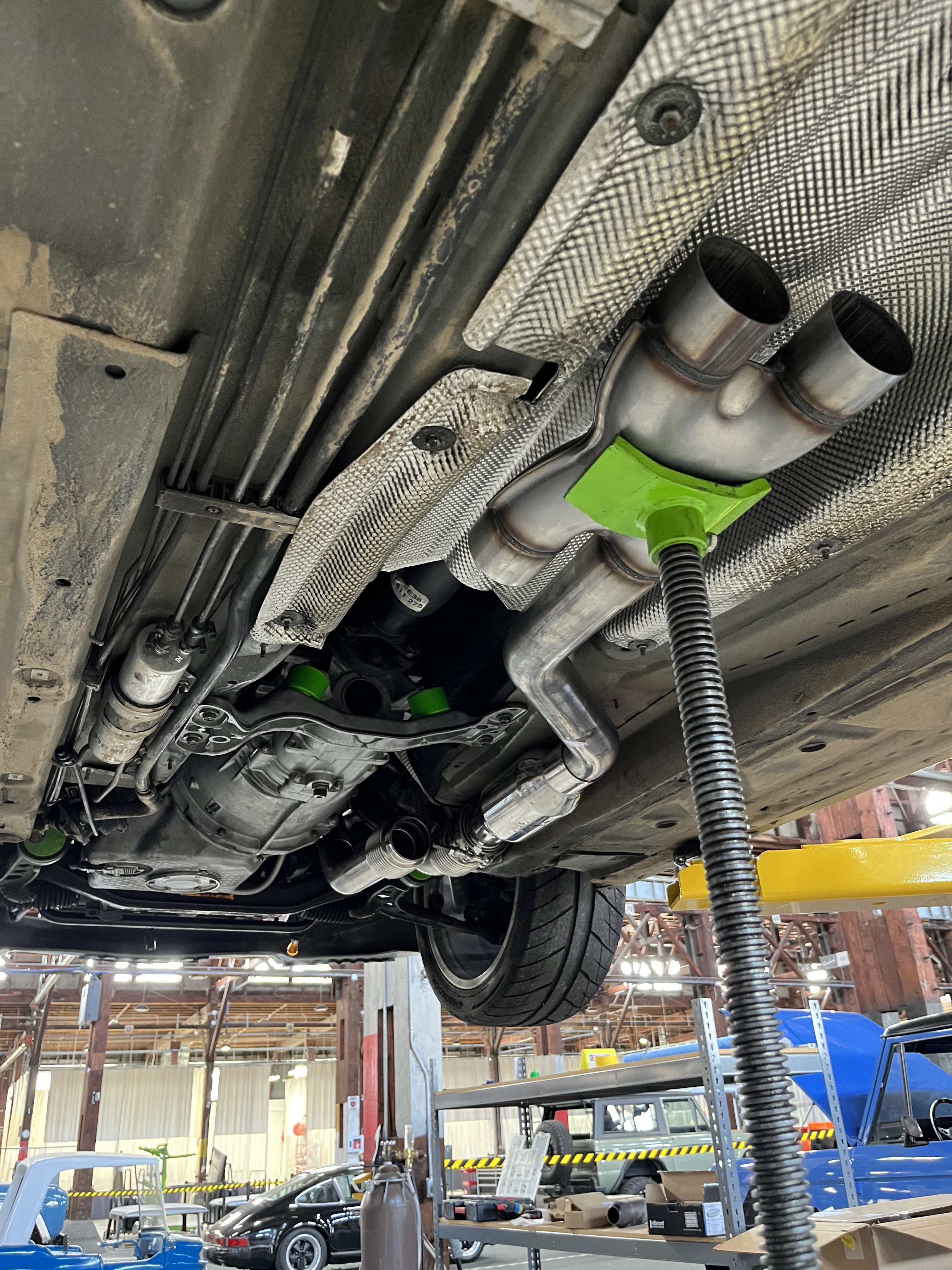
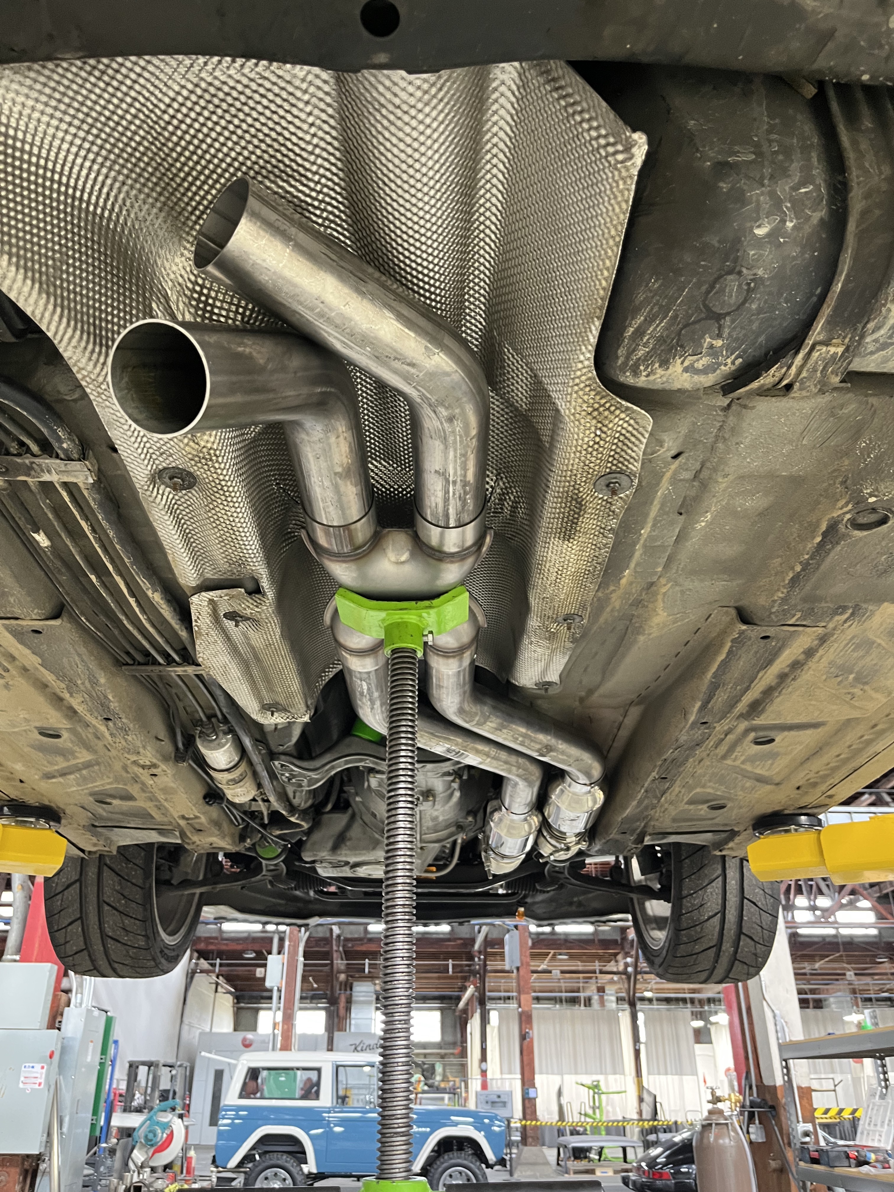
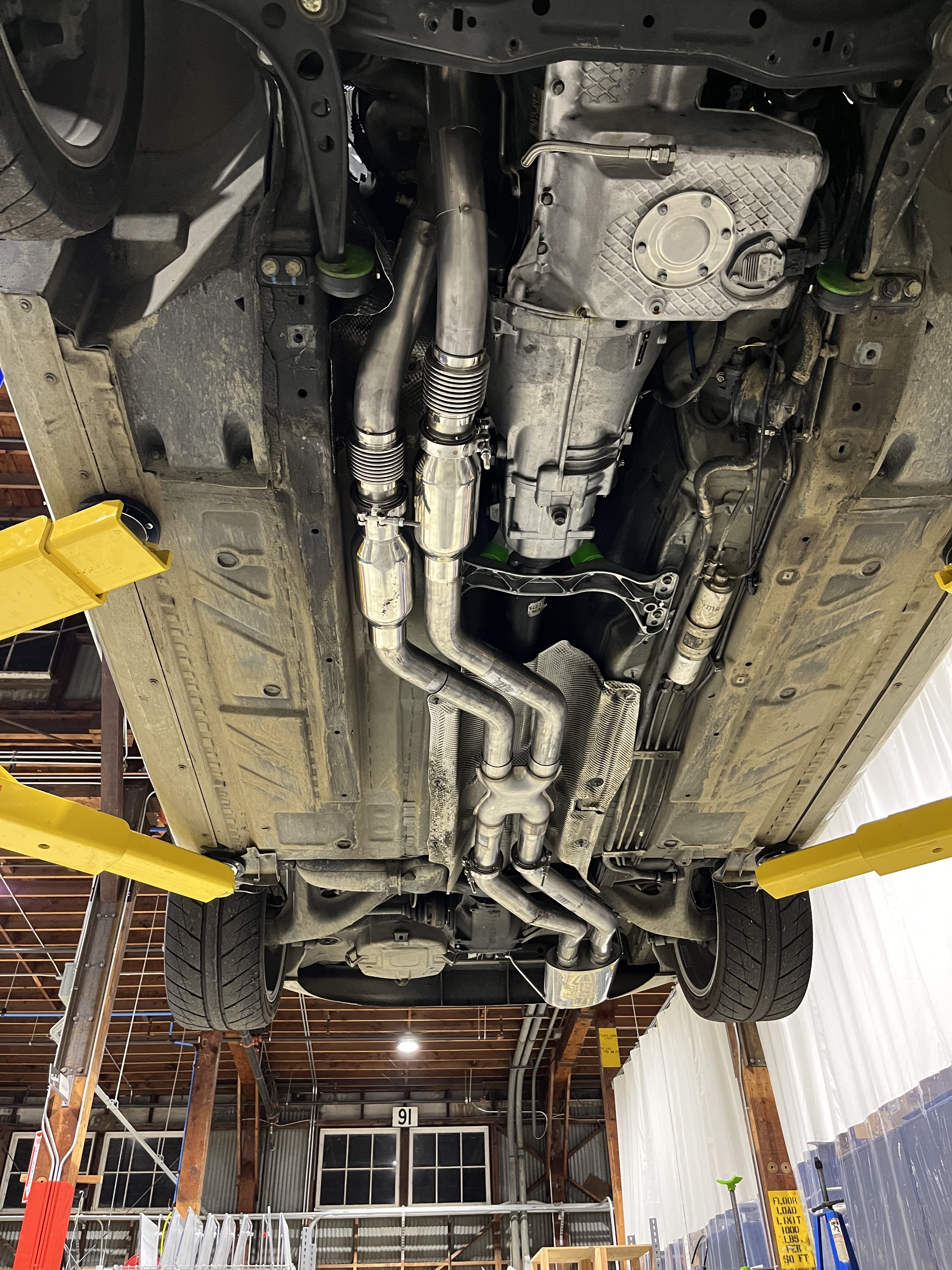
Shortly after finishing V1.0 of the exhaust, I realized that it was far too loud, specifically for the sound regulations at Laguna. I added an additional muffler and mounted the system more securely to the transmission and rear subframe using custom exhaust mounts.
Freeflow Peristaltic Pump
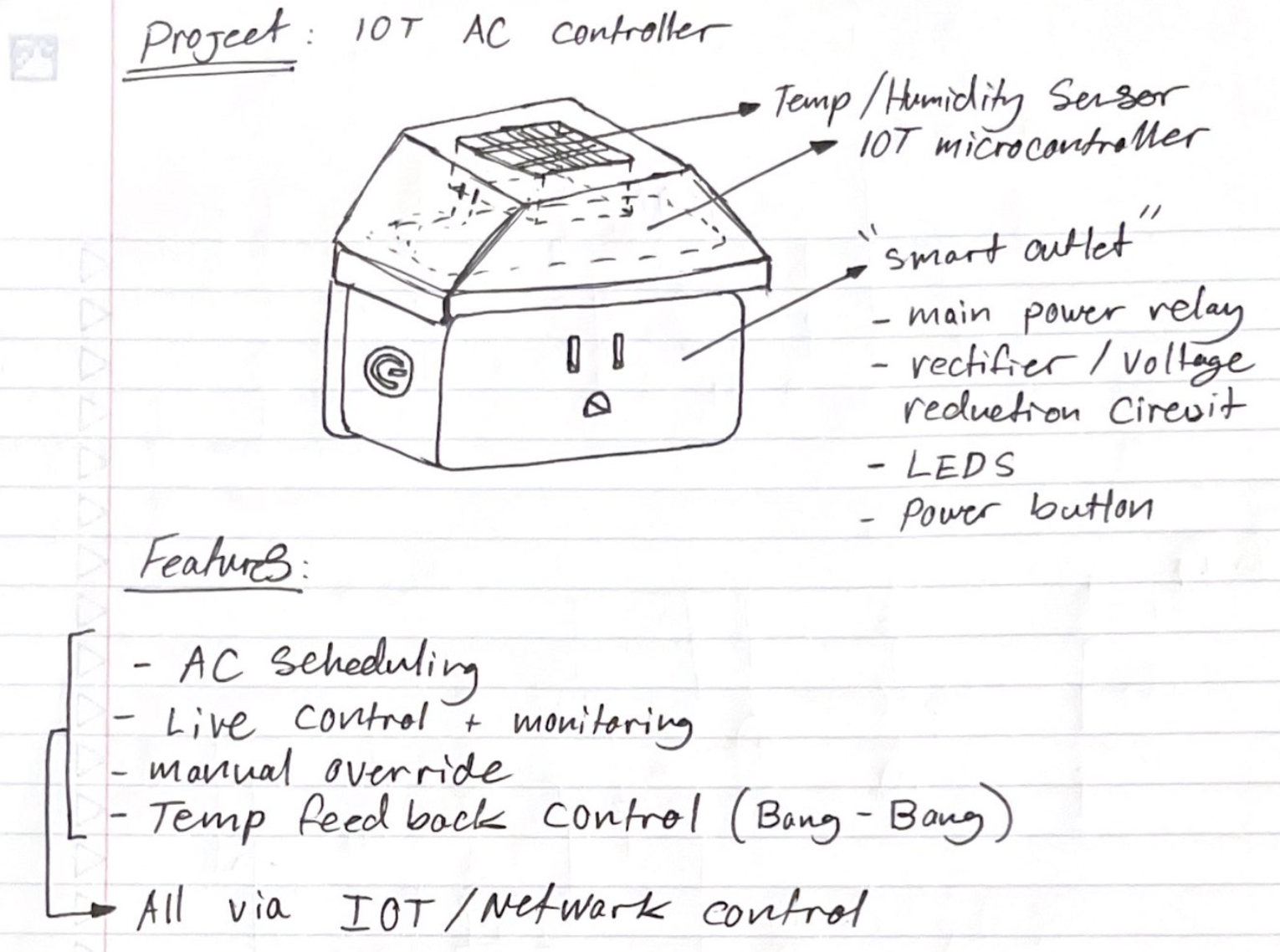
IoT enabled, temperature sensing AC controller
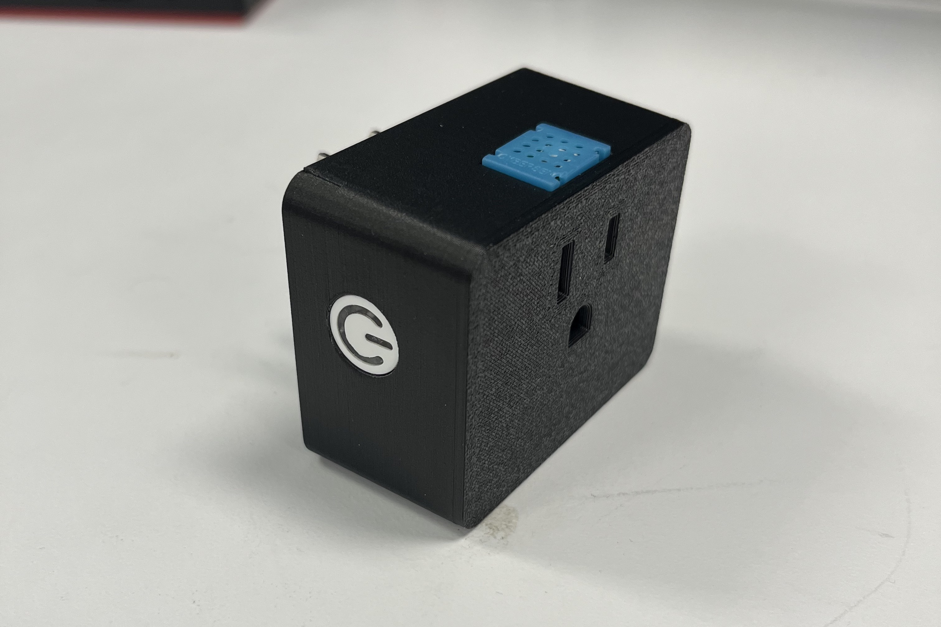
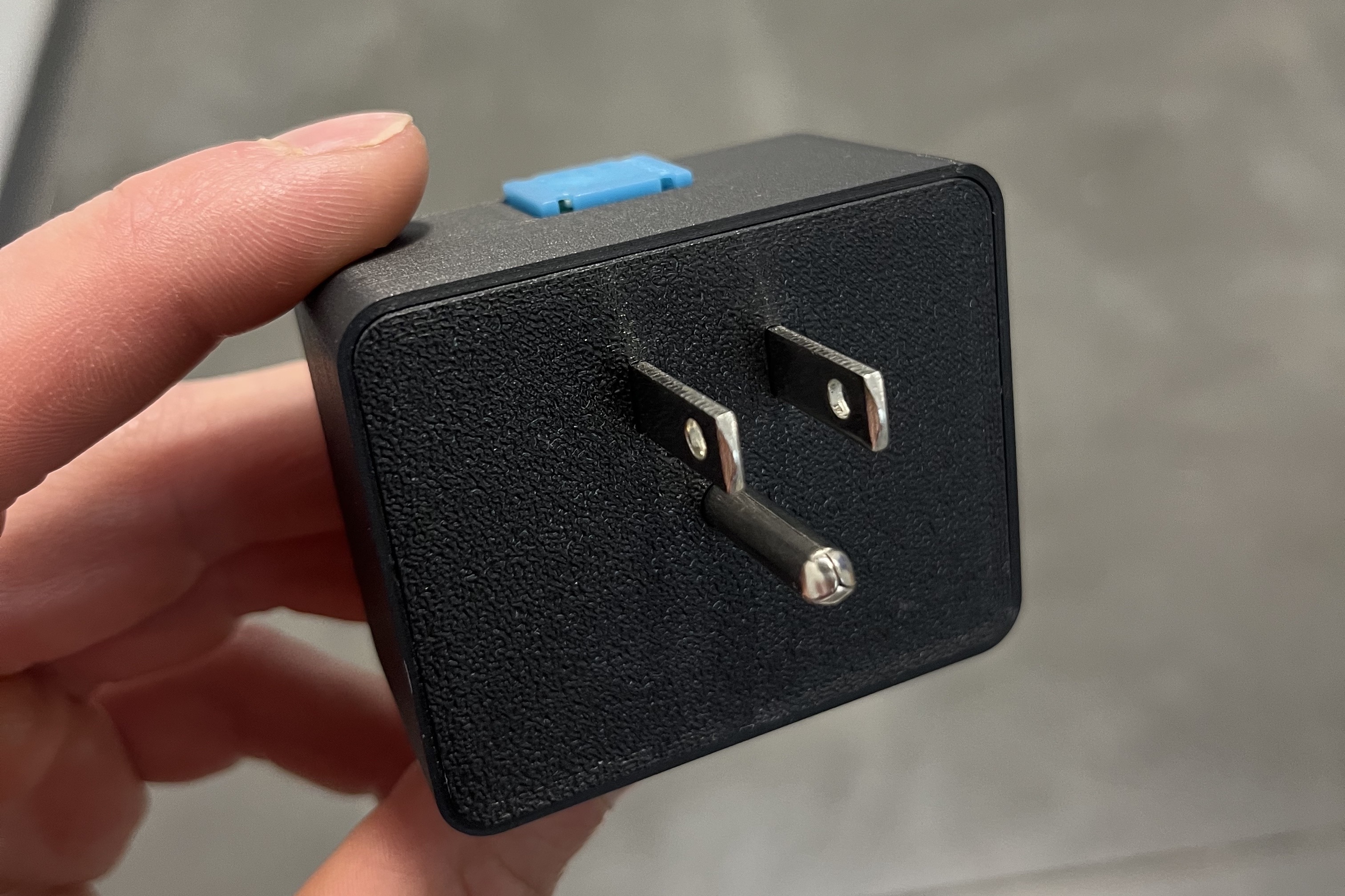
I created an IoT enabled smart outlet that measures temperature and humidity to control an in-window AC unit.
Project History
Hardware:
For my main system architecture I used a WiFi enabled ESP32 module, allowing me to adjust requested temperature, monitor the status of my room and AC unit, and manually control the unit from anywhere via a mobile app. For temperature and humidity monitoring, I used the incredibly common DHT11 sensor, which was easy to power using 5V and easy to read using my ESP module.
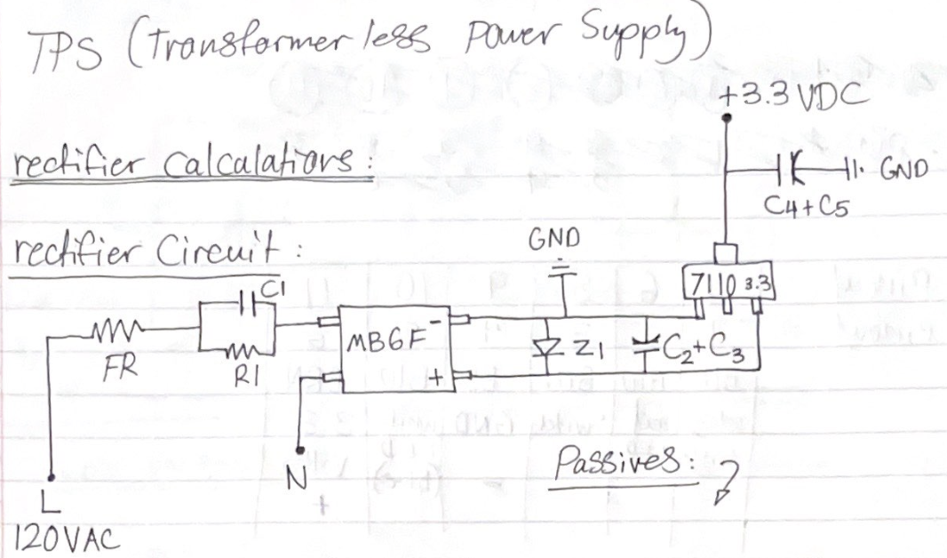
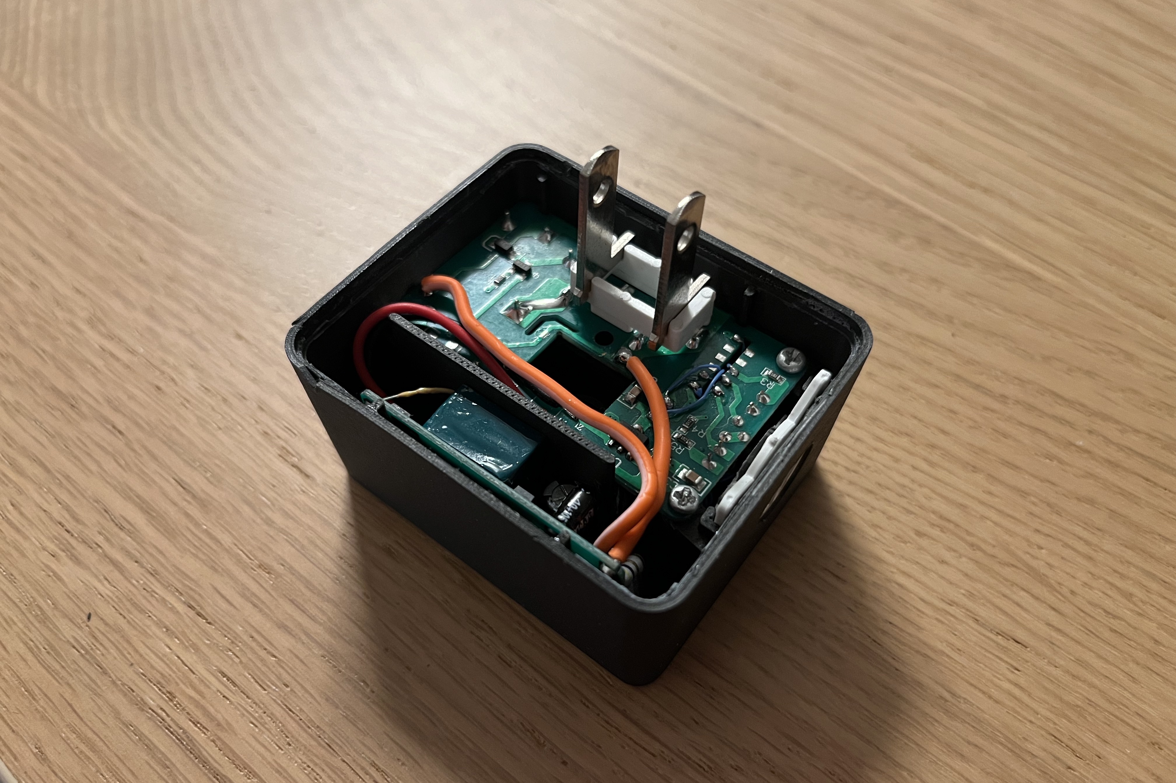
For the power supply circuitry, I started with a circuit I pulled from an off the shelf switched outlet. This unit already had a transformerless power supply, consisting of an MB6F full bridge rectifier to convert the 120VAC to around 24VDC, a HM7110 3.3V voltage regulator to supply power to the small microcontroller onboard, A relay linked to a S8050 J3Y NPN transistor, and a few passives and diodes to tie it all together. I began by mapping out the circuit and grabbing datasheets for the main components. I quickly realized that the transformerless power supply design is fundamentally suited for ultra low current draw equipment, and that the ESP32, that regularly pulls over 300mA during WiFi activities, was ill-suited for this type of power supply, which would brown out and cause the ESP32 to reset every time a WiFi command was executed.
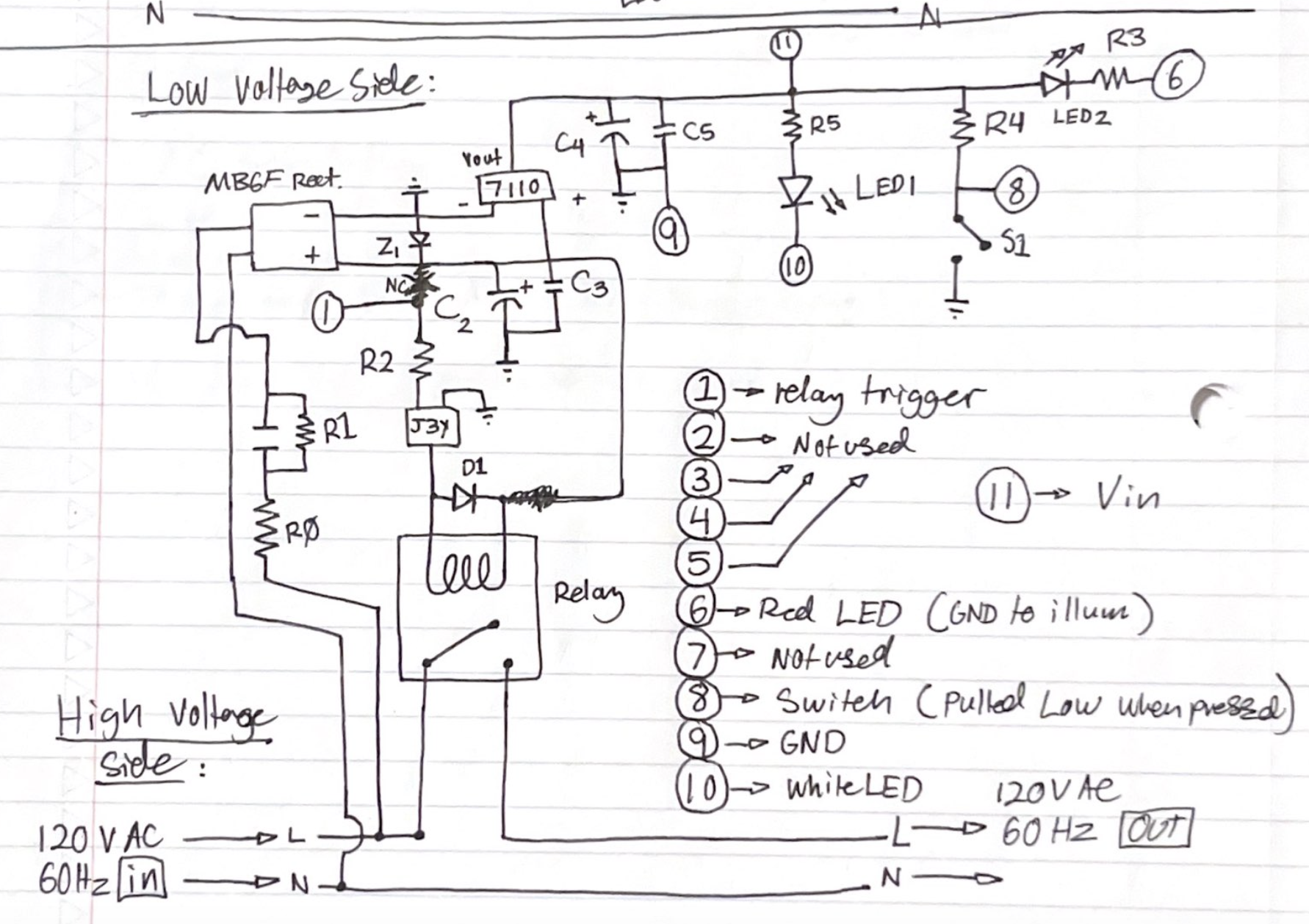
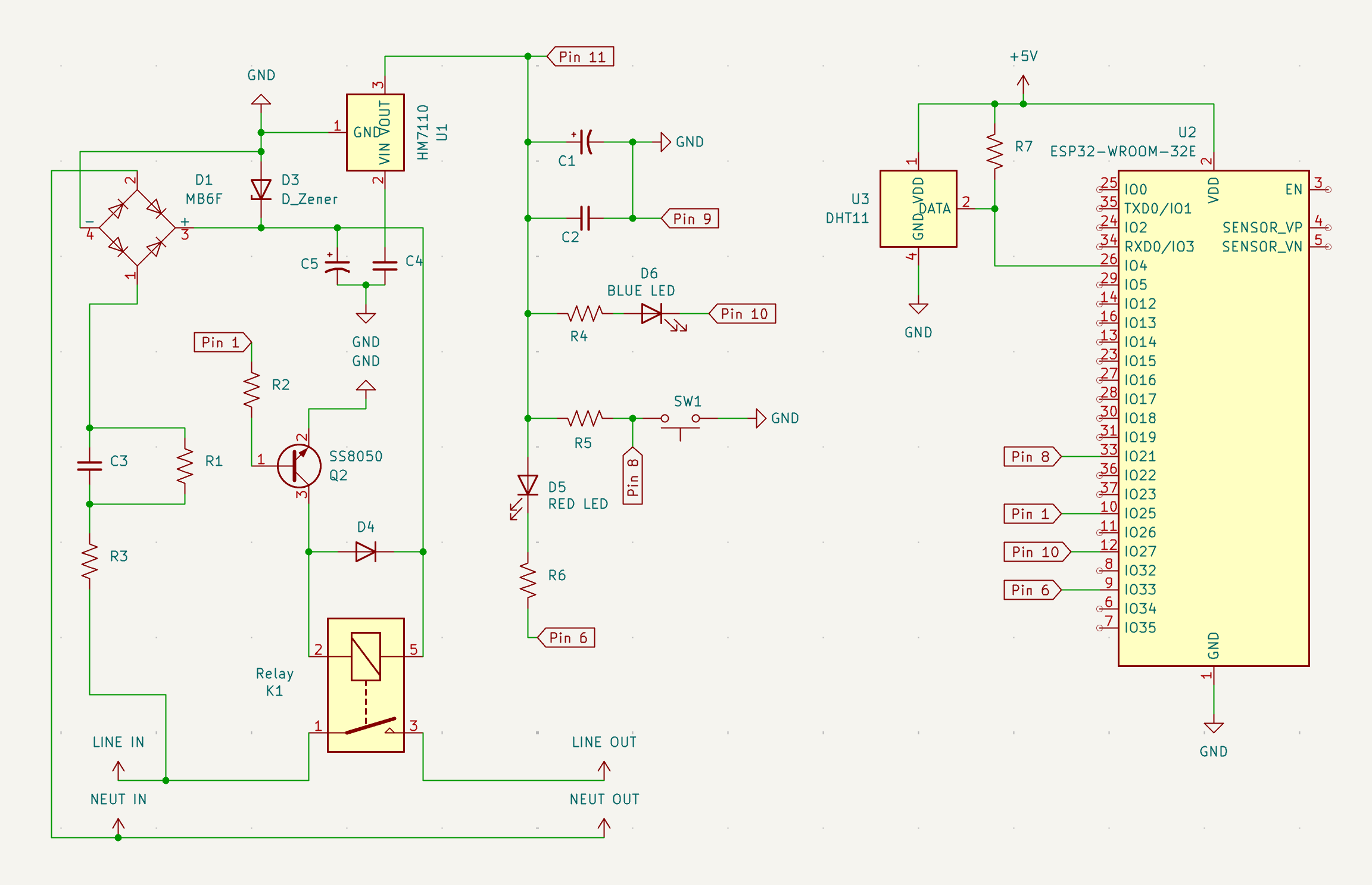
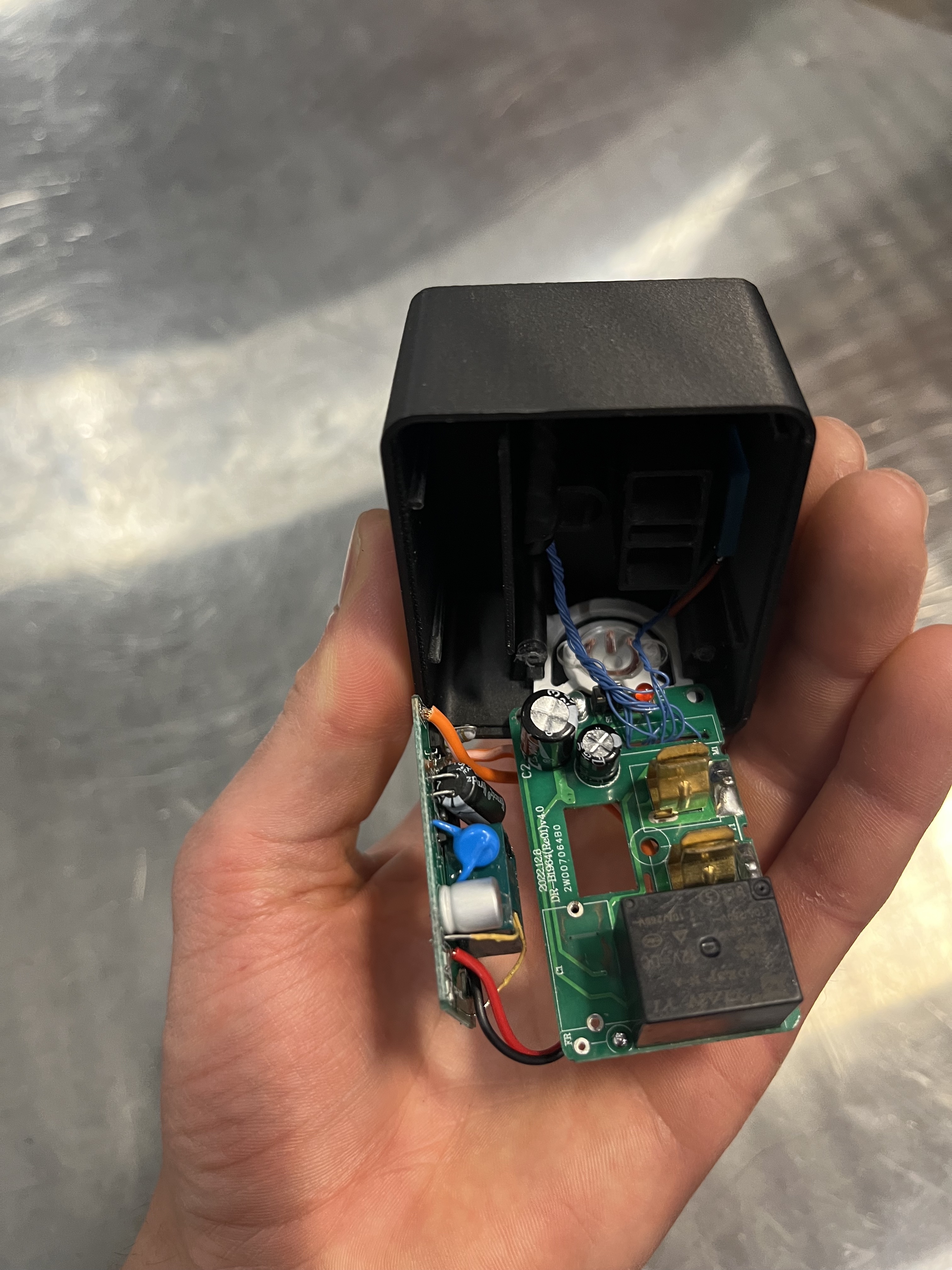
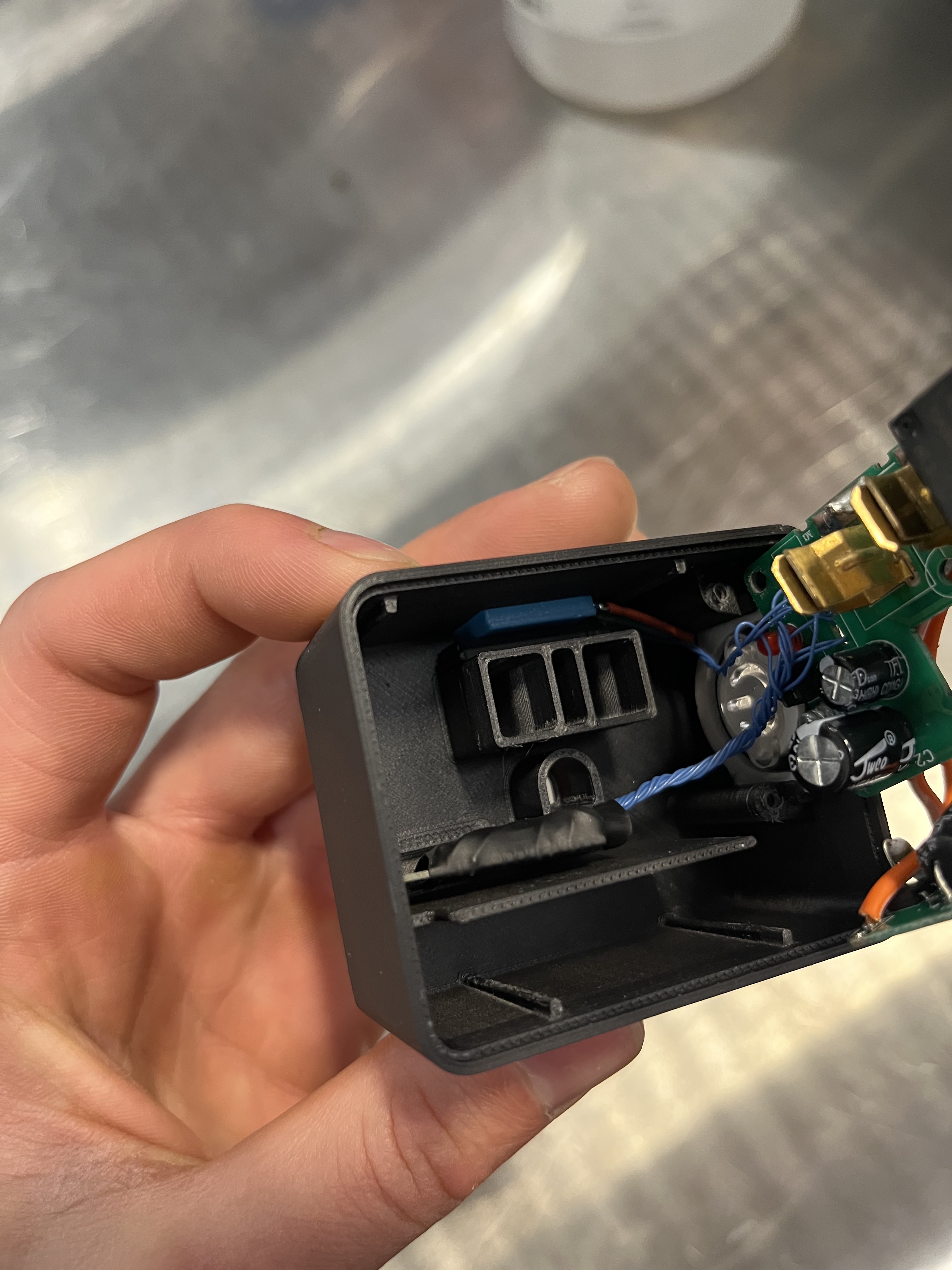
I decided to scrap the idea of just piggybacking off the existing power circuitry, and added a small 5V switching supply pulled from a phone charger, plenty capable of providing up to 1000mA at 5V, more than the ESP32 module could ever pull. For safety I completely desoldered the existing transformerless supply, and kept only the LEDs, pushbutton, and relay on the main board, desoldering the existing microcontroller and connecting the ESP32 to traces leading to the remaining components. I chose to place the raw module, insulated with heat shrink tubing, in its own compartment, with physical barriers isolating it from the high voltage circuitry and small jumper wires connecting the two boards and the small switching power supply to the ESP32.
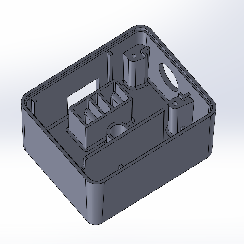
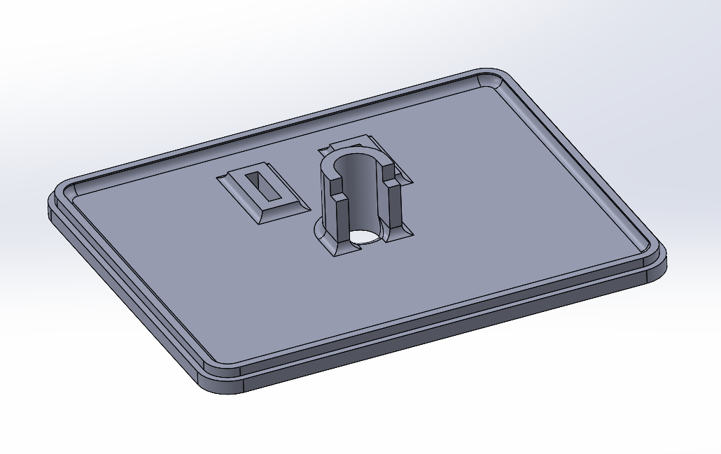
The housing was modeled in SolidWorks, Although I designed the housing with draft angles, intended to be injection molded, I printed the prototype model in two parts with a standard FDM 3D printer in black ABS. The components are held in using two small screws and a compliant mechanism, and the case was fused together using solvent welding with cyclohexanone. The pushbutton cover was taken from the off-the-shelf smart outlet unit, and features a clear window to view the LED indicators, and a satisfying click when pressing the pushbutton. The temperature/humidity sensor is lodged in place via a compliant mechanism.
Firmware:
The firmware was written in the Arduino IDE, and is available here:
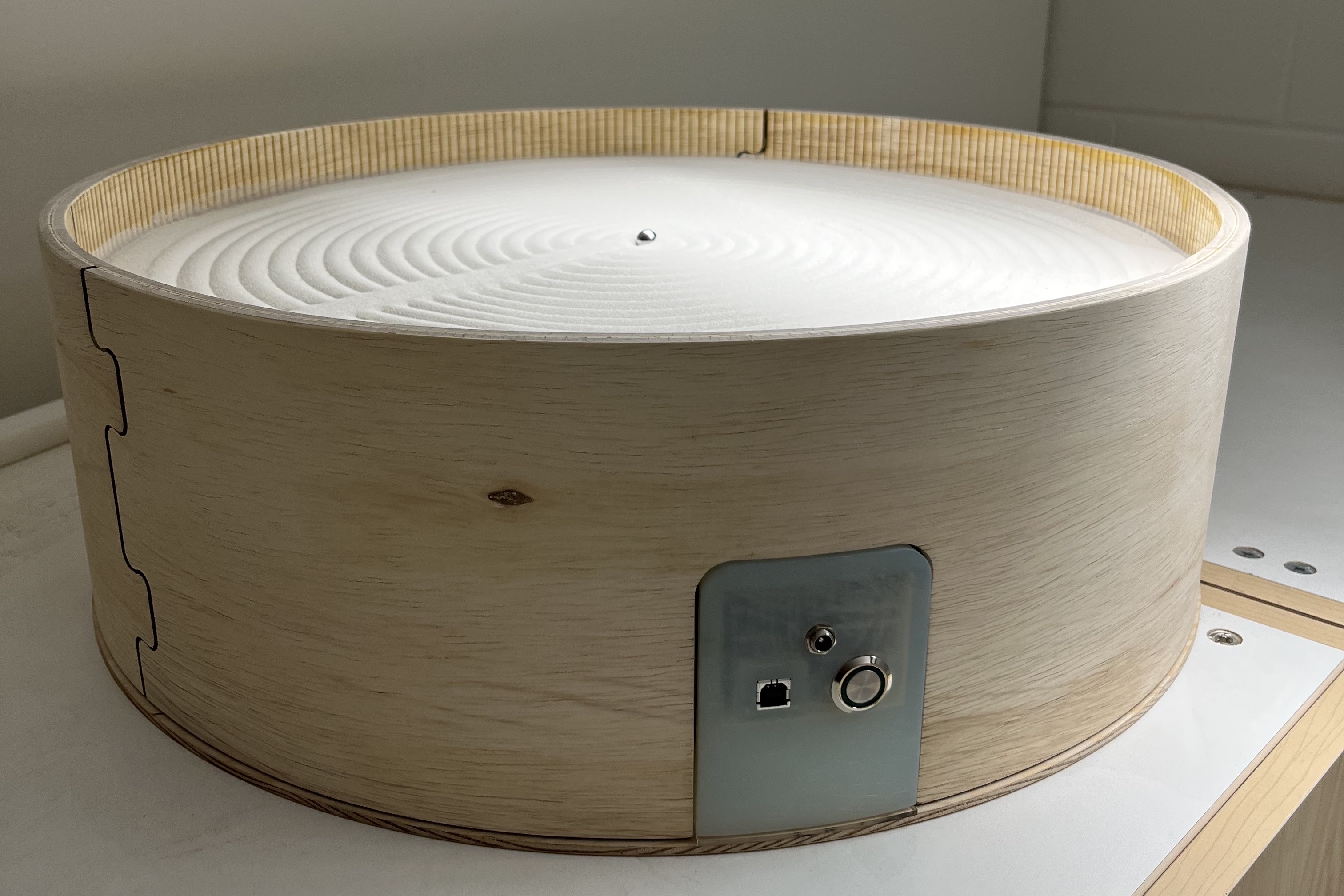
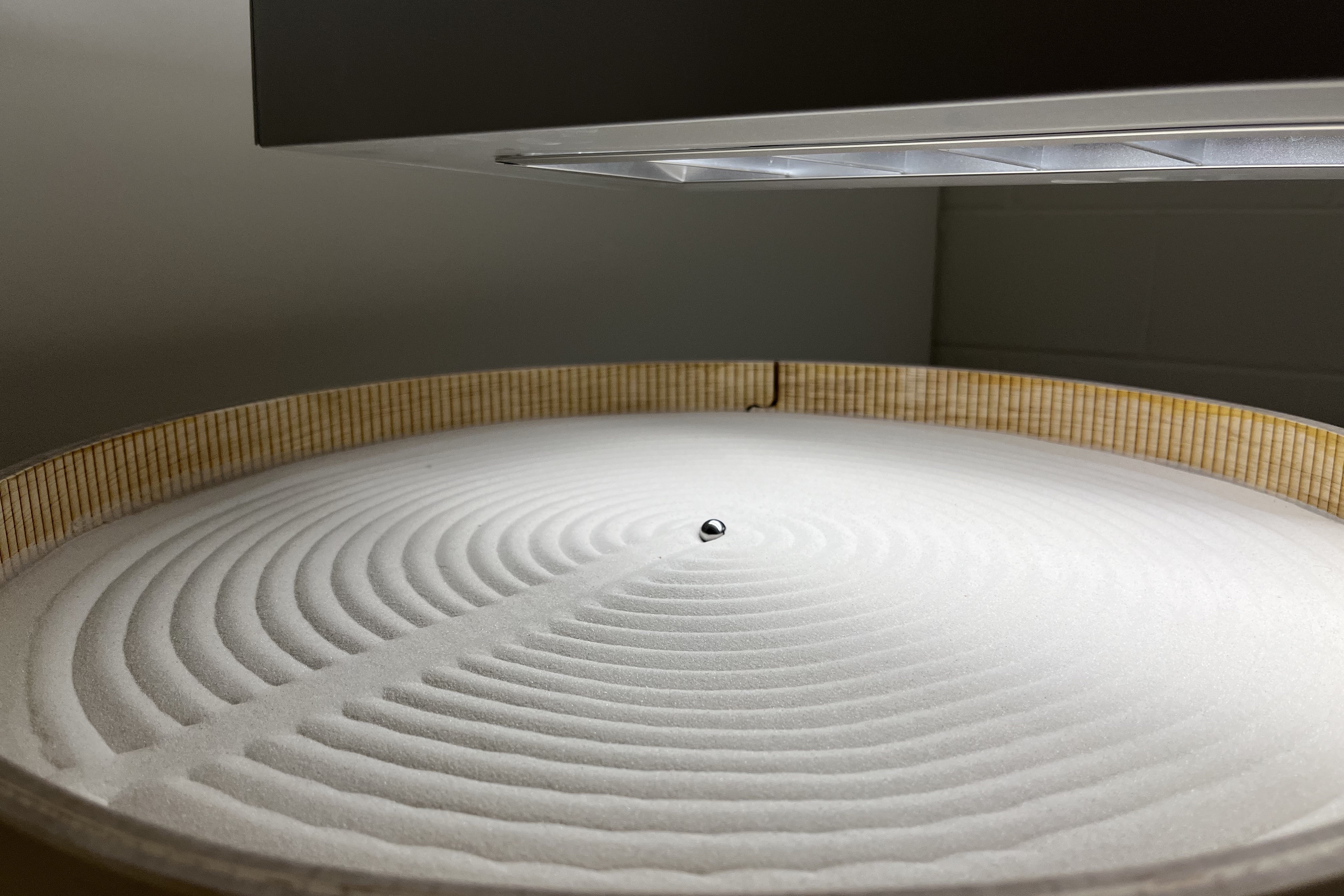
Made-From-Scratch Sisyphus table
I made a robotically controlled Zen garden style sand table, also known as a Sisyphus table, that uses a robotic gantry attached to a magnet to pull a steel ball bearing through a thin layer of sand.
Project History
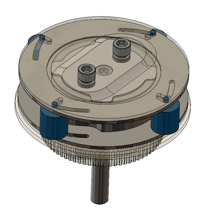
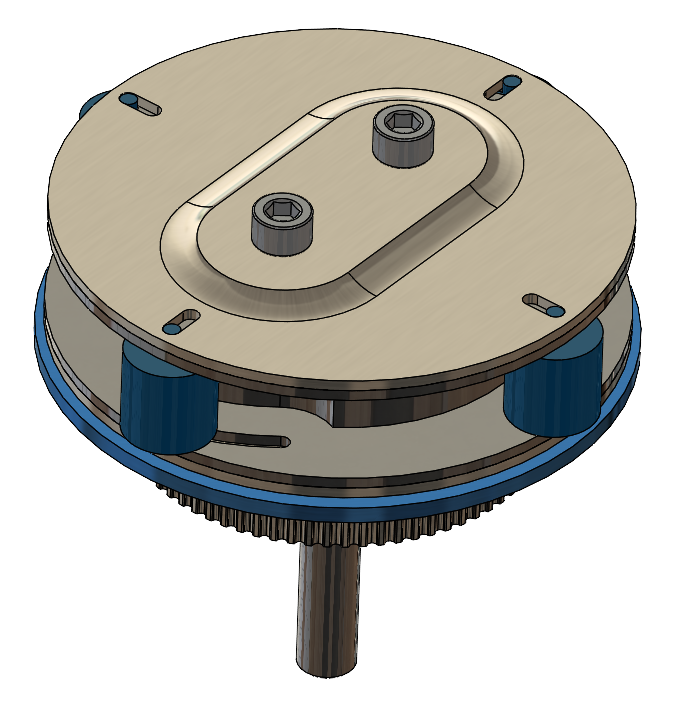
A partner and I built all aspects of this project from scratch, including: designing a custom PCB to utilize stepper motor controllers, power circuitry, and an AVR microcontroller. Programming the board from scratch in embedded C and flashing using AVRdude, writing several custom libraries to control each subsystem. Designing and manufacturing the polar coordinate gantry, running my own CNC programs to manufacture a set of custom parts and to modify off-the-shelf ones. And finally, doing some woodworking, wood CNC, laser scoring, and additive manufacturing to create the cylindrical housing.
Hardware
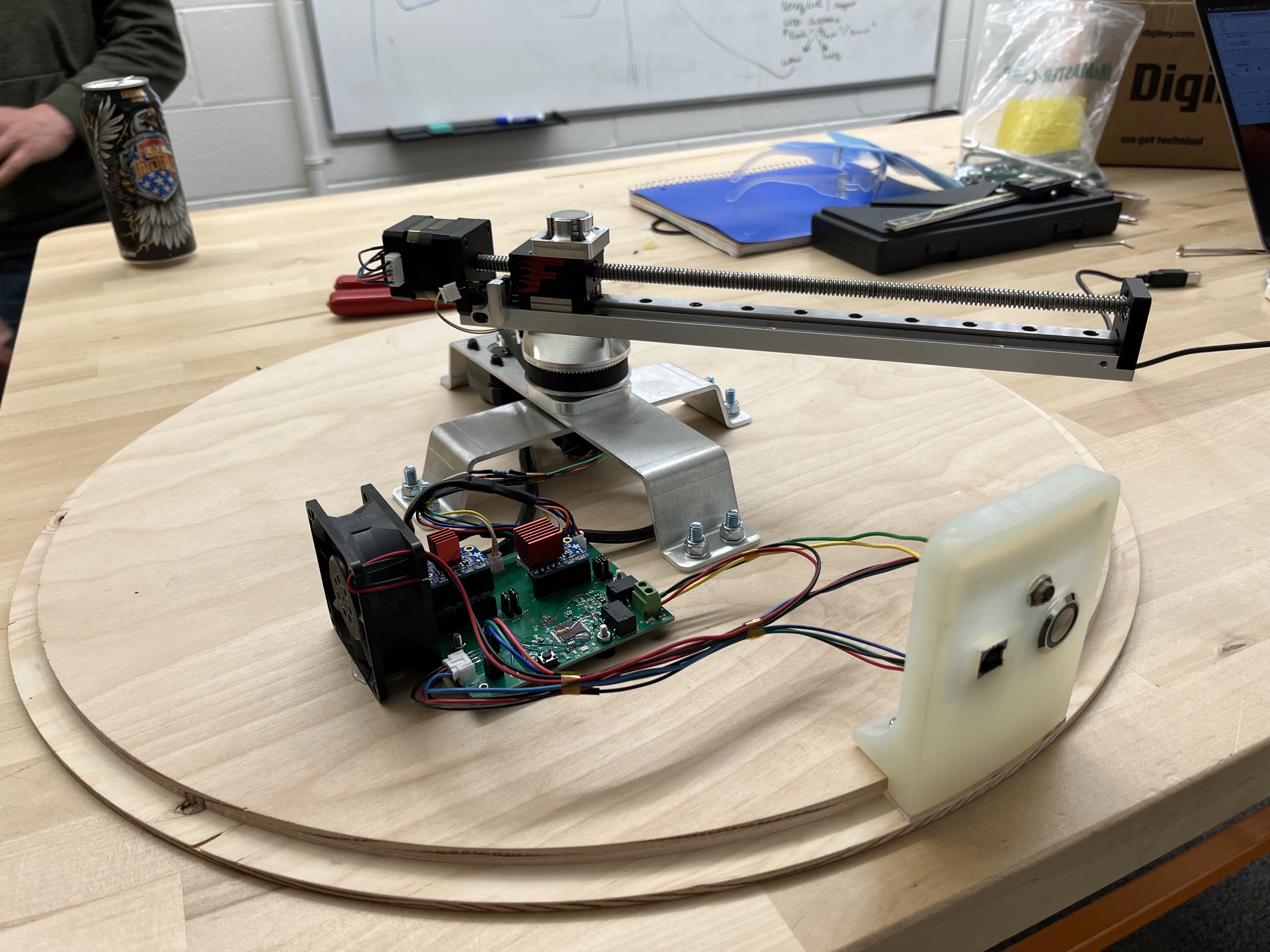
The gantry and interface panels were built using a combination of resin 3D printing, CNC machining, and sheet metal bending. The printed and CNC-machined components were manufactured by me on a Formlabs Form 3 and a Haas Mini Mill 3-axis CNC. I contracted out the manufacture of the sheet metal components to SendCutSend. The entire assembly was designed in SolidWorks prior to ordering any materials.
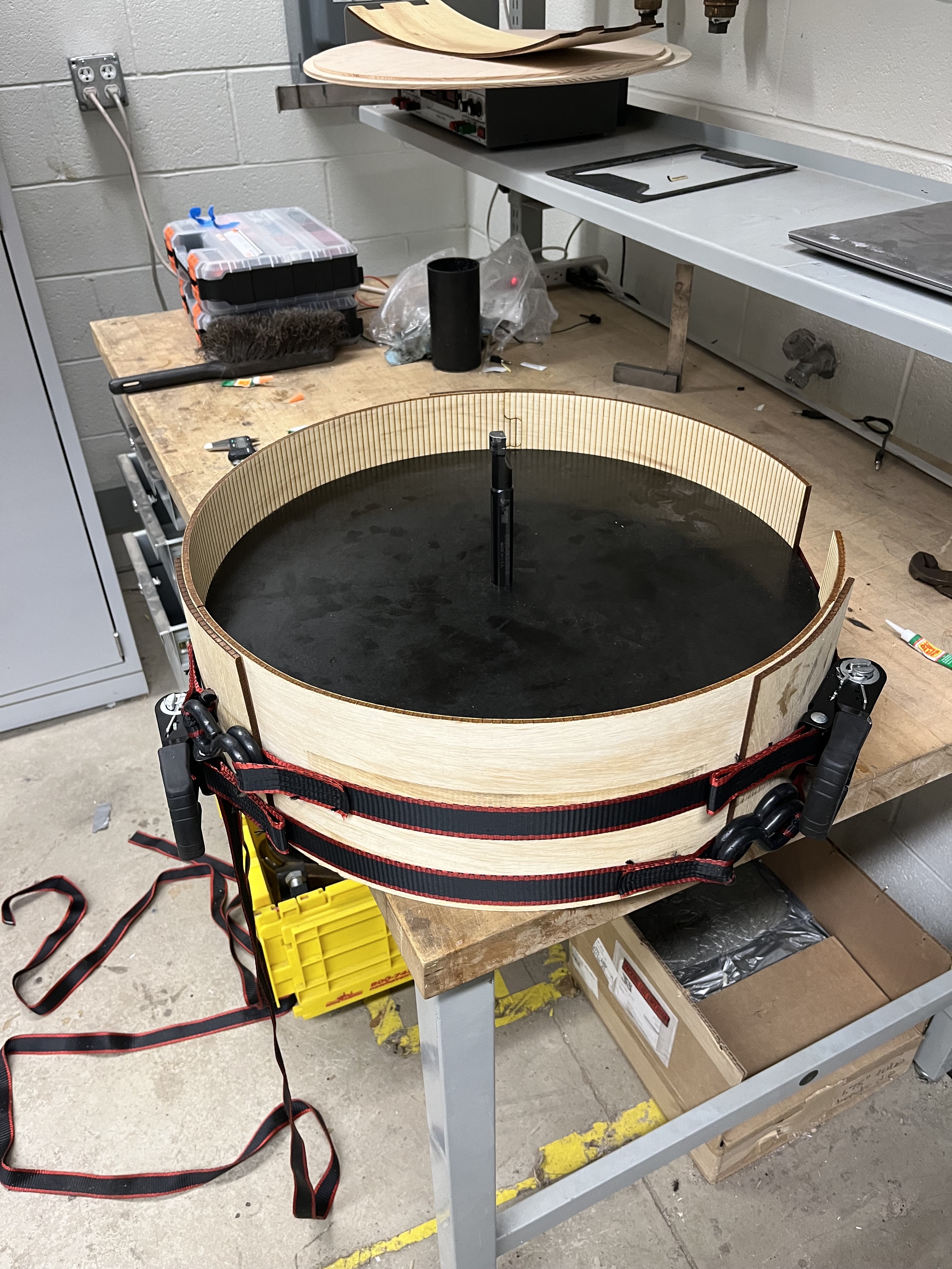
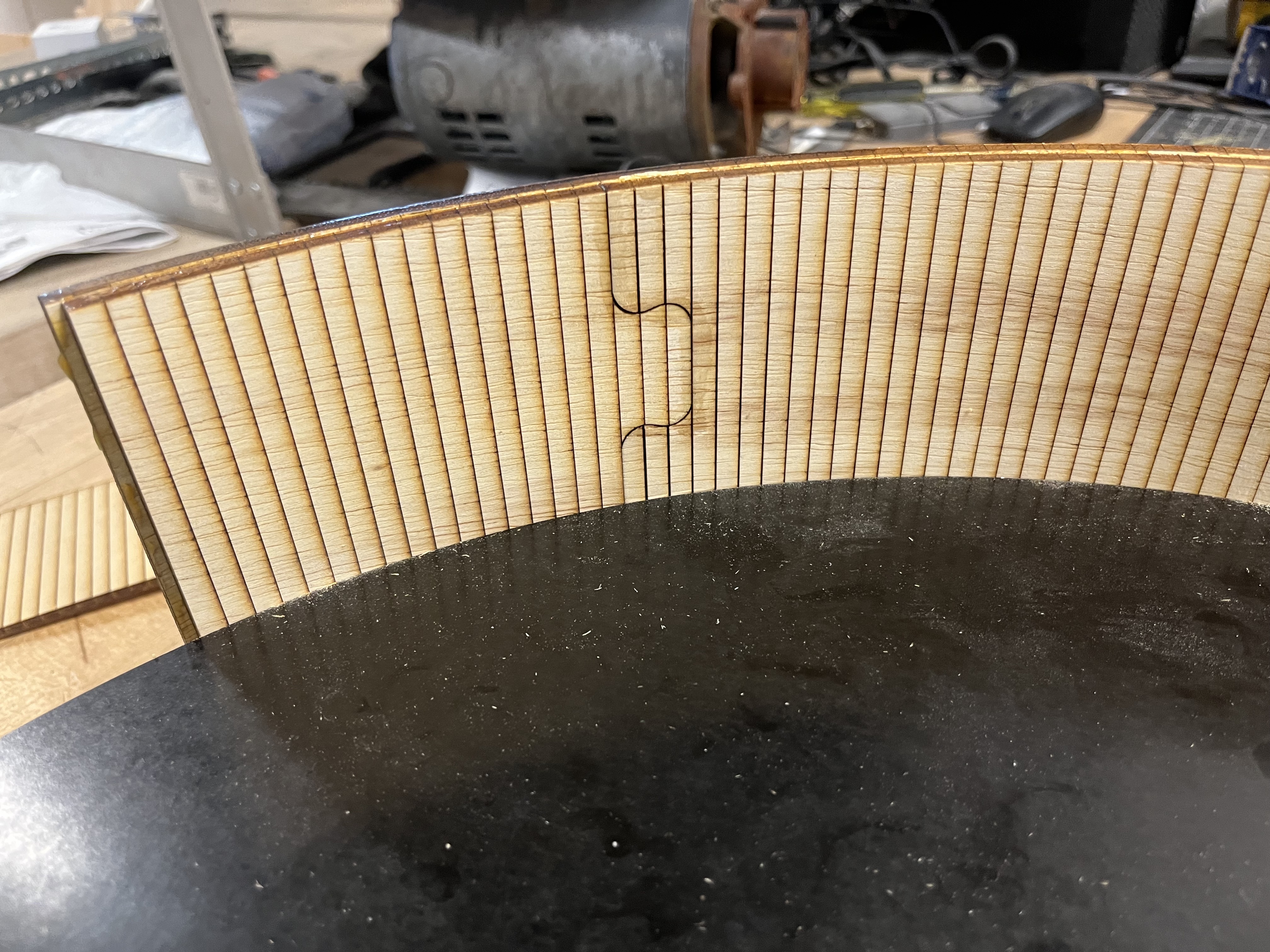
The outer housing was constructed from 1/4" and 1/2" plywood using a combination of laser cutting and scoring techniques, and CNC machining with the help of a ShopBot wood CNC router. The cylindrical outer structure and sand support plate were cut on the laser, using laser scoring to give them flexibility. Circular forms were machined from MDF on the ShopBot to assist in the glue-up of the scored components. This laser scoring process takes advantage of the draft angles left when cutting wood with a laser. When three-layer plywood is scored but not fully cut through, a trapezoidal void is left in the plywood, bisecting both the top layer of veneer and the mid layer, leaving the base veneer intact. I aligned the grain of the bottom veneer to maximize strength along the axis of the bend, and performed testing using different score spacing to achieve the best bend radius that aligned with my housing design. In this case, the spacing was about 1/4".
Custom Folding Car Camper
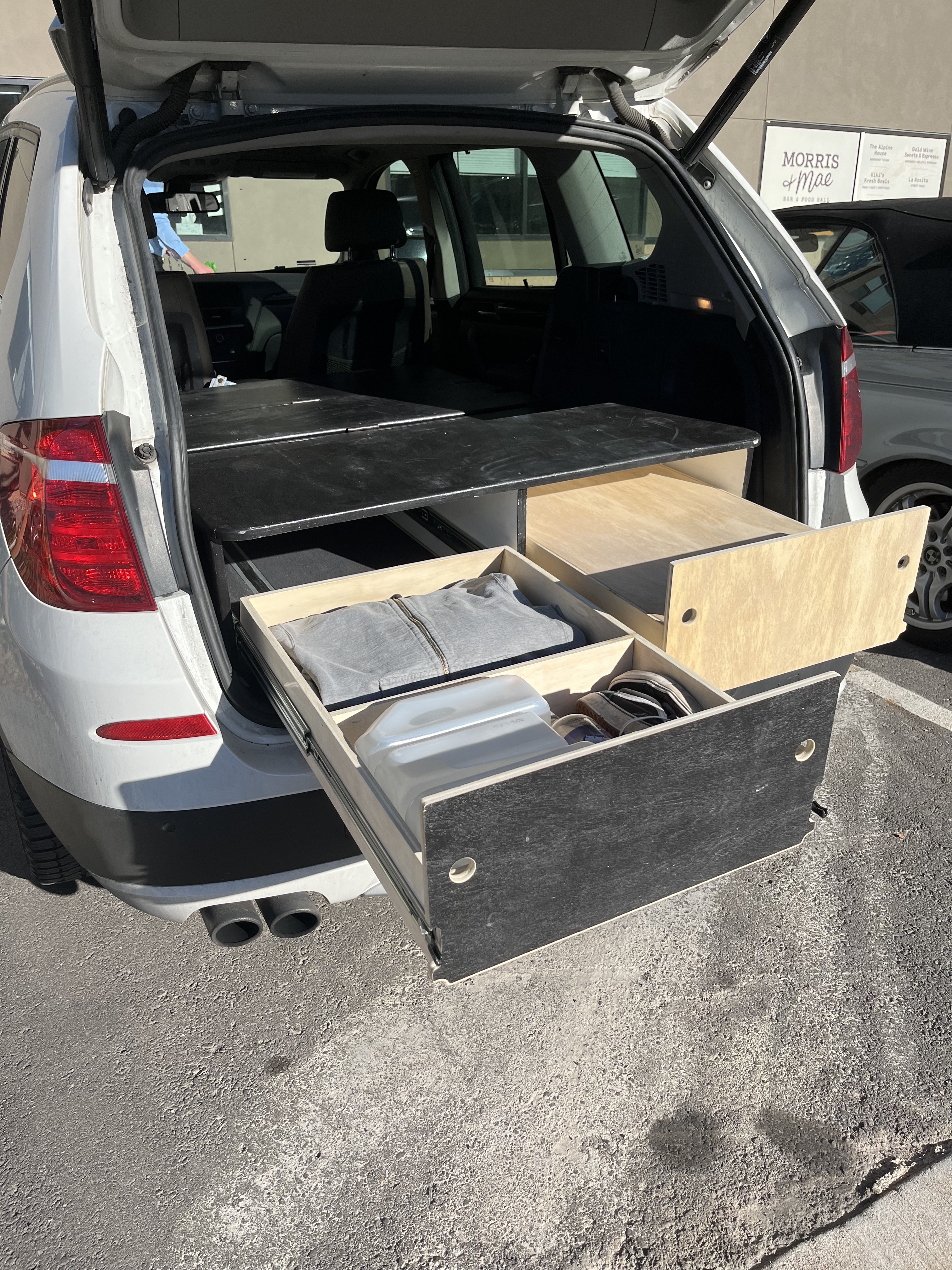
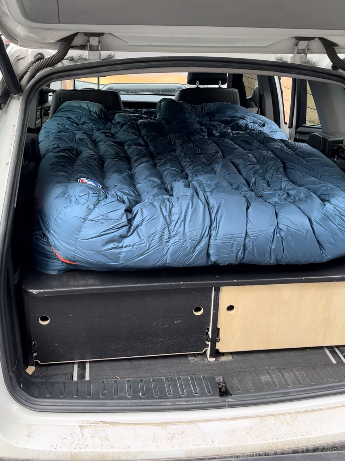
I built a custom car camping solution for my SUV, the system allows for comfortable sleep on climbing trips and has provisions for storage of cooking supplies and climbing equipment while the folding capability allows use of the rear seats.
Project History
I built a custom car camping solution for my SUV. The system allows for comfortable sleep on climbing trips and has provisions for storage of cooking supplies and climbing equipment, while the folding capability allows use of the rear seats. I designed and built the main platform in the spring of 2020, but did not complete the locking drawer system until 2023.
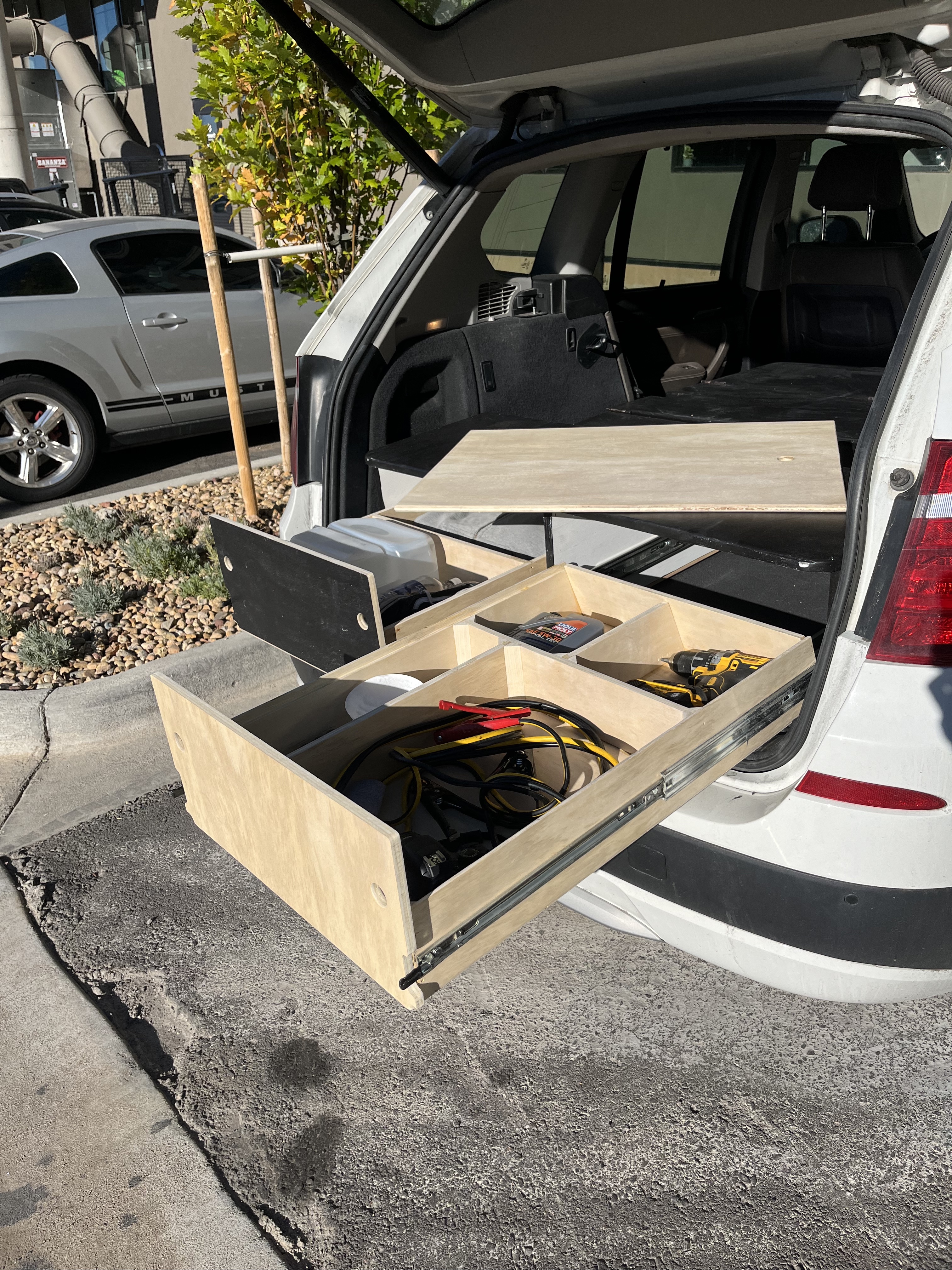
The main platform is constructed from 3/4" plywood, finished with black exterior paint and white interior paint, and is built in three sections separated by hinges. This allows the setup to fold up inside the car without contacting the headliner and stow in the trunk, out of sight, when not used. When you want to set up the bed, you simply put down the rear seats and unfold the structure to reveal a flat surface to sleep on.
I designed the system in SolidWorks using measurements of my car, a 2013 BMW X3, but it has fit in most SUVs I have tried it in. The drawers were added later and are made from 1/2" plywood, supported by 120 lb drawer slides. The left drawer is general purpose and has two zones: one for tall items and one for short items. The right drawer has zones specifically designed to fit my camping stove, pots, cleaning supplies, spatulas and knives, and cooking fuel.
The right drawer also has a finished piece of plywood that serves both as a lid for the drawer and as a surface to cook on. The drawers were both designed in SolidWorks and added to the assembly before purchasing material, and are fully removable for easy reconfiguration.
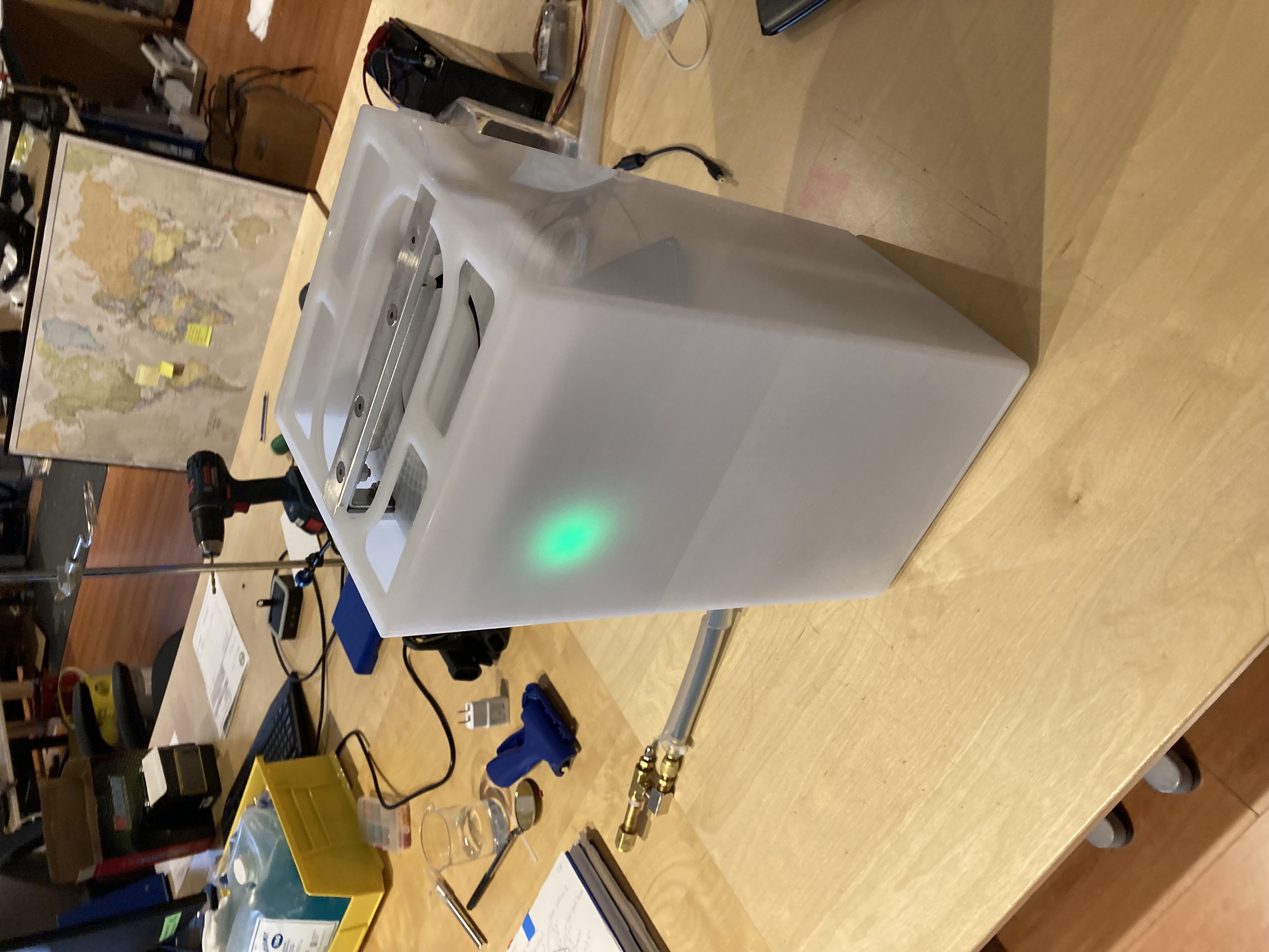
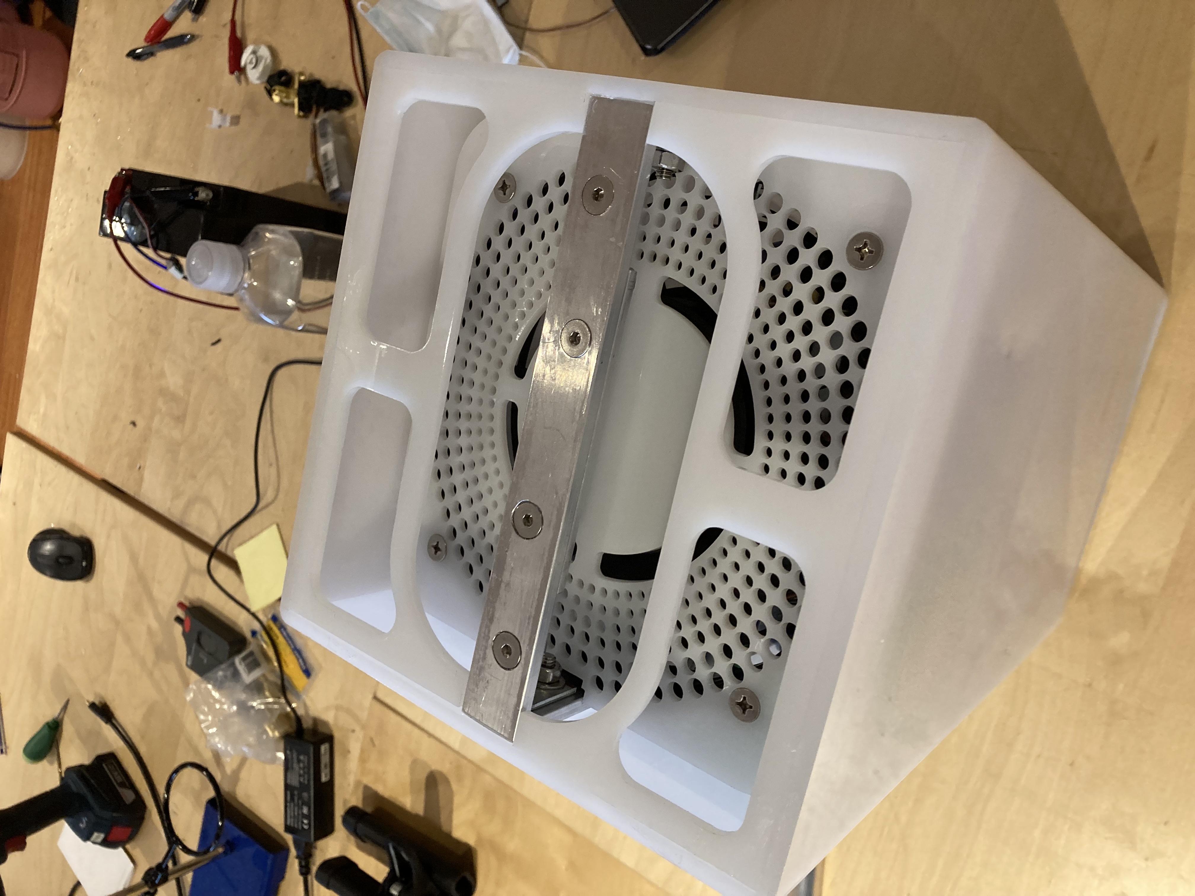
Portable Cryoablation System
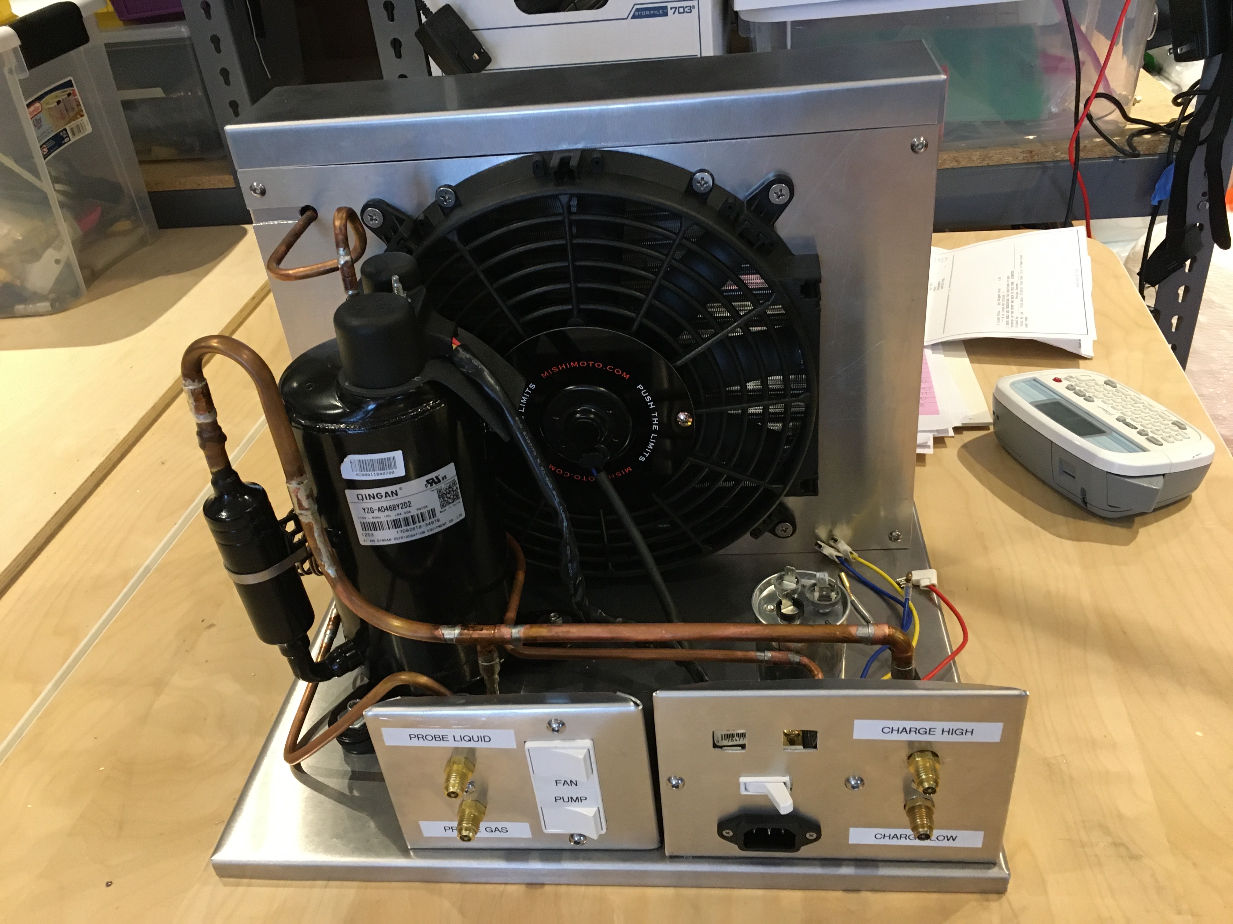
While working with Ananya Health, I developed a portable Cryoablation system designed to treat cervical cancer in areas without access to refrigerant gas infrastructure or reliable power. The device went through many iterations while I was with the company. Starting with a few proof-of-concept models that used standard components from R410A refrigeration systems. These devices ran on typical 120VAC/60Hz power and used compressors, condensers, and filter/drier units from in-window AC units. The evaporator was replaced with a thin PEEK flow restriction tube, a copper probe, and an expansion sleeve. This concentrated the cooling power of the evaporating working fluid in one area, making it useful for freezing or ablation of cancerous lesions on the cervix.
The first devices overpreformed the specification required for cryoablation, reaching -40 degrees celcius in under a minute, and providing over 10,000 to 14,000 BTU of cooling capacity. They served as a fantastic demonstration of the potential for portable closed-loop cryoablative devices, and, along with the skillful work of our team, helped garner the company funding to continue our research and a spot in the Y-Combinator class of 2021. I am pleased to say I had an instrumental role in the early days of Ananya Health and contributed greatly to the success of our technology.
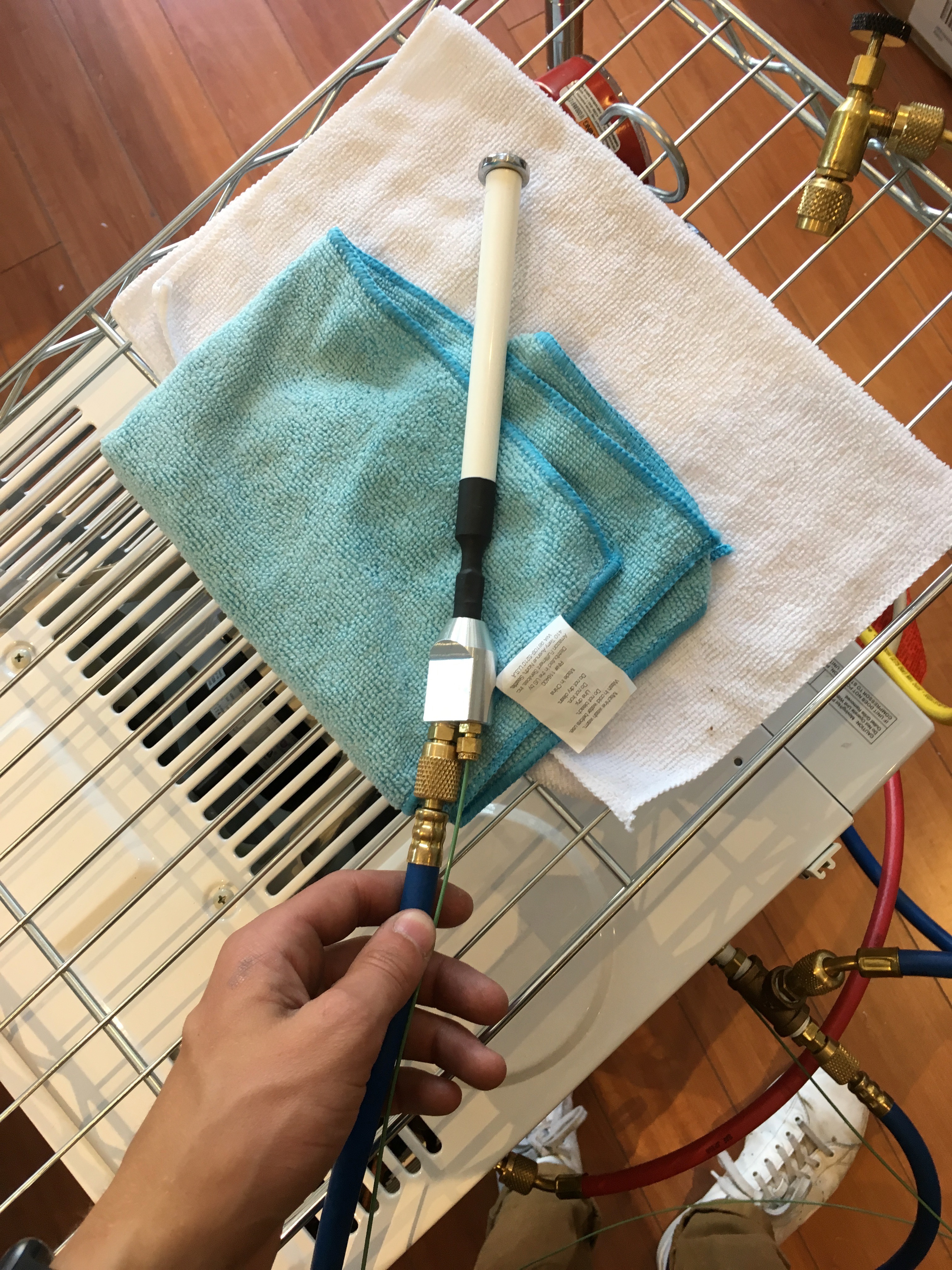
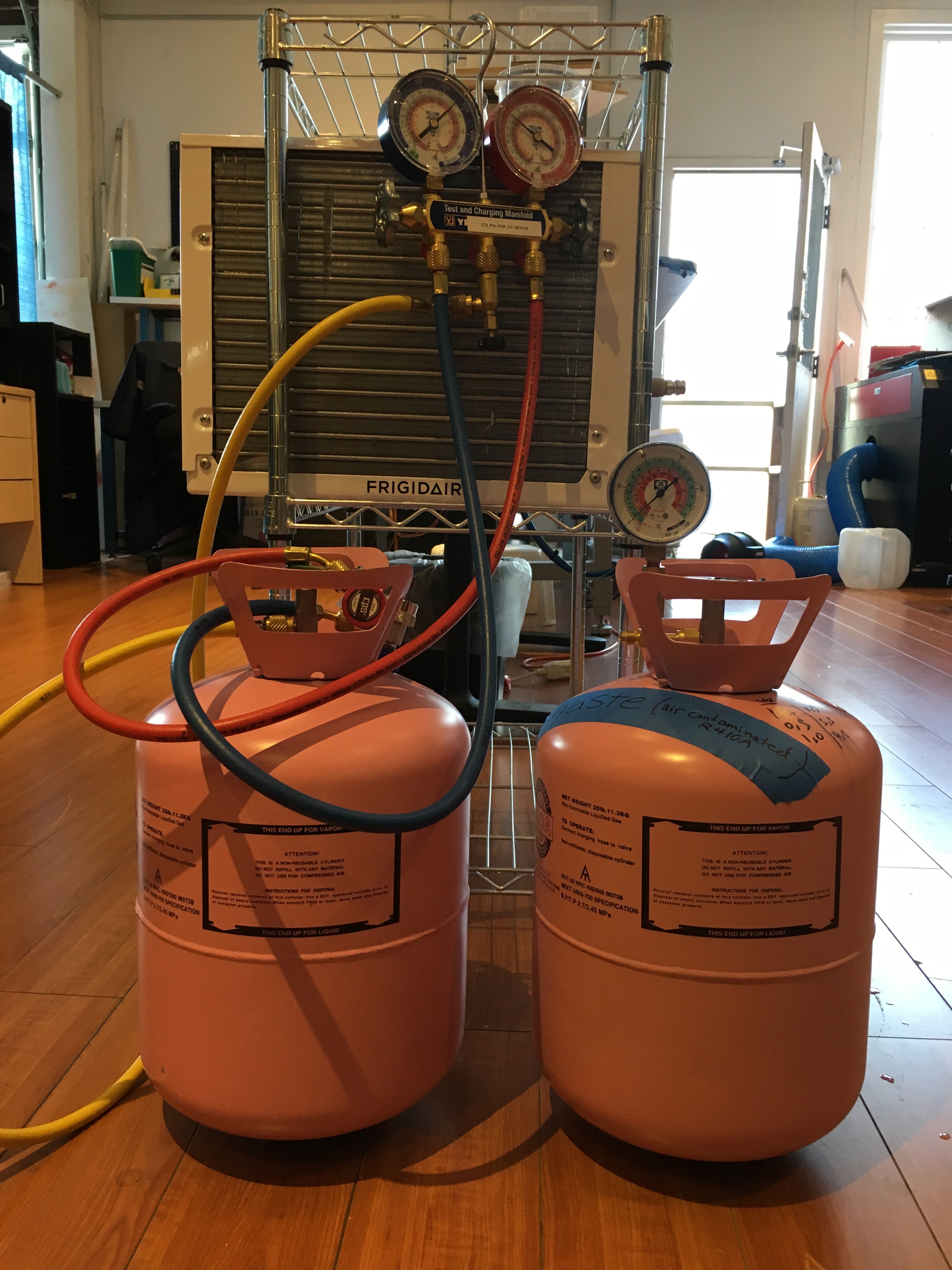
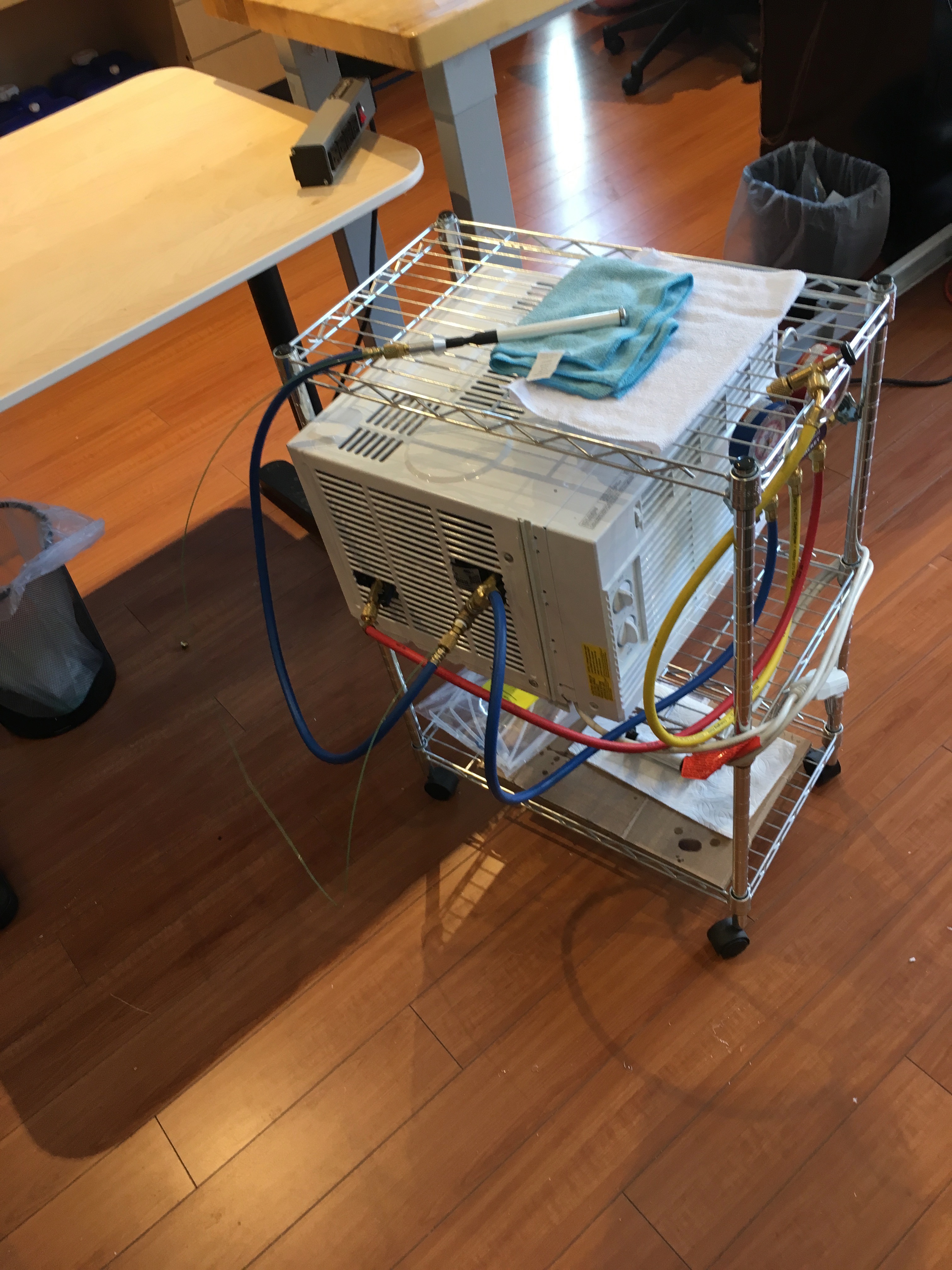
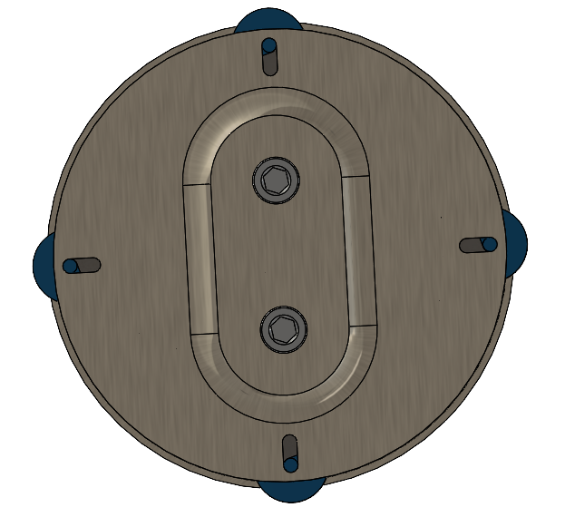
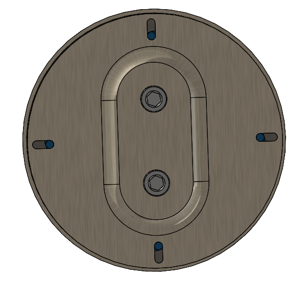
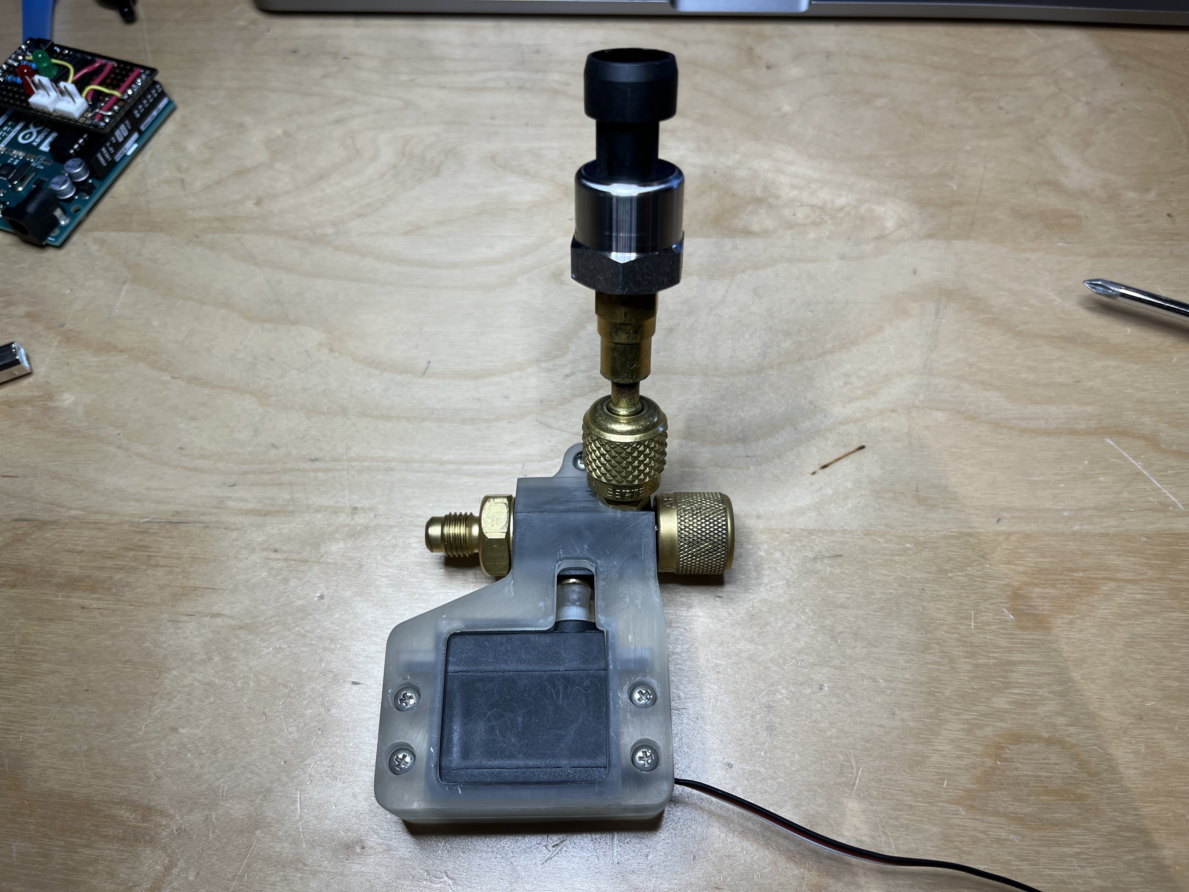
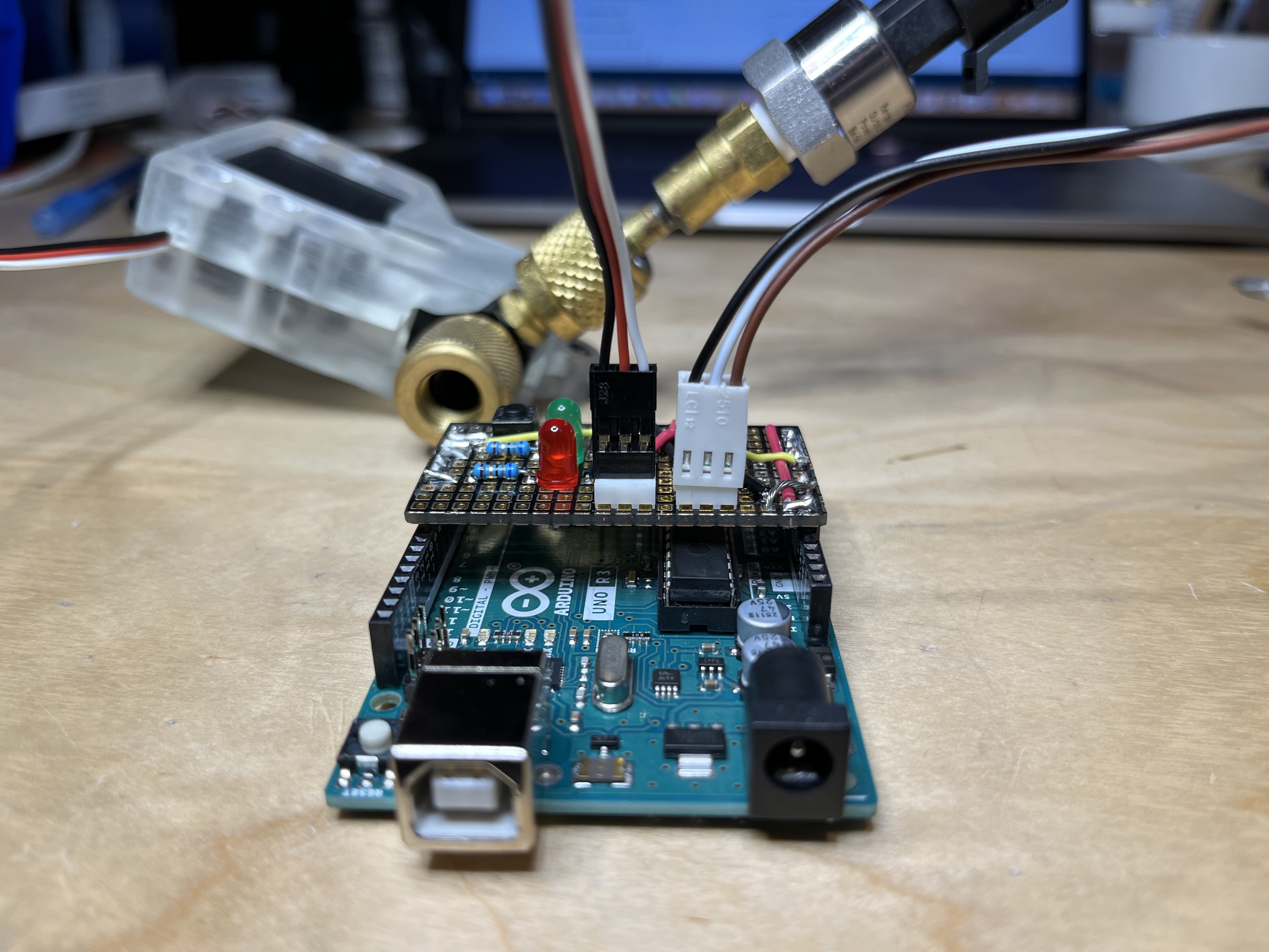
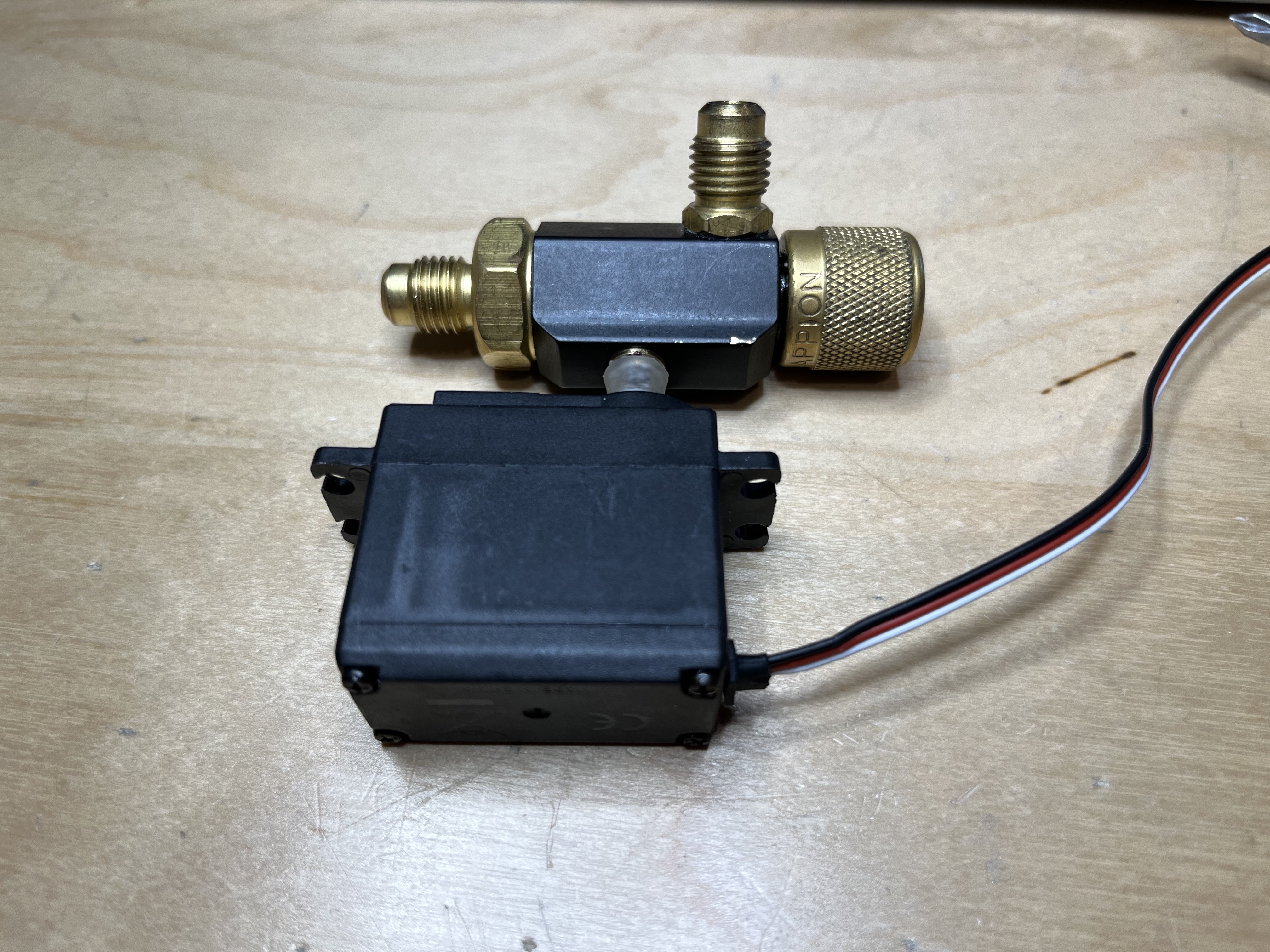
When I returned to Ananya Health during the following summers, the goal was to optimize our system for lower power consumption and a smaller form factor while still preserving the efficacy of our earlier devices. This was done utilizing a fully modular system that the team built to isolate individual components during testing protocols. The component size, operating voltage, refrigerant type, internal volume, ratio of volumes of different regions, working fluid mass, and many other variables were evaluated systematically by our team during this period. One of the devices we tested in our system was an electronic throttling controller, a device designed to automatically open and close the valve, allowing refrigerant to flow through the PEEK tubing to the probe tip.
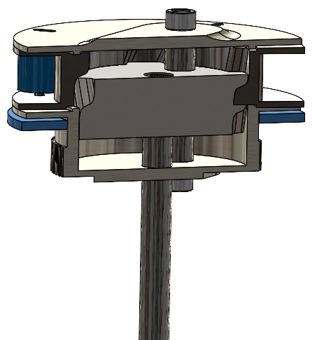
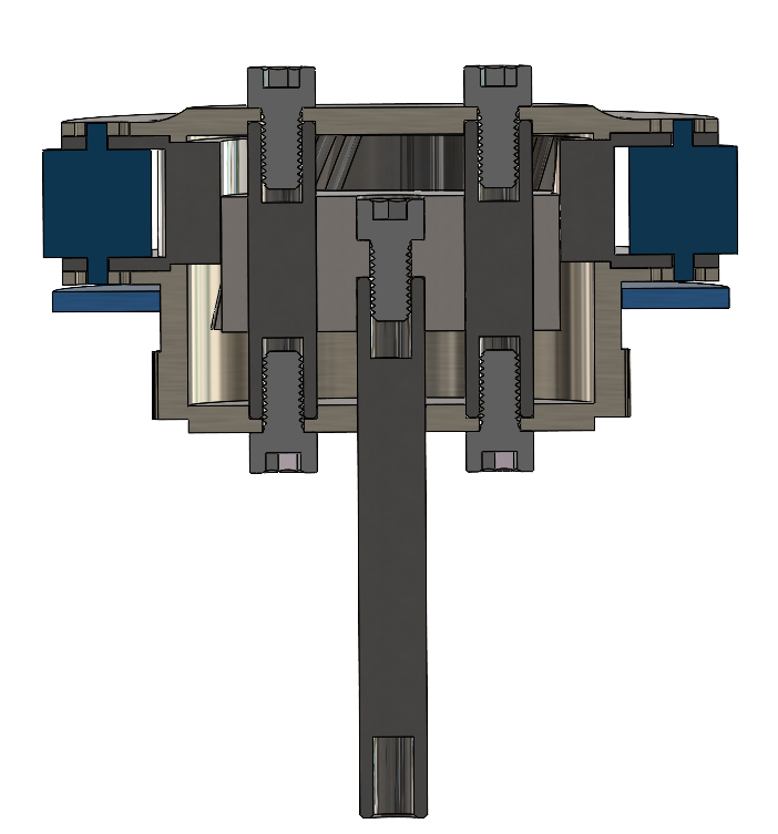
The theory here was straightforward: we had chosen a new working fluid due to its availability, environmental safety, and low toxicity, but we were having issues with our new refrigerant's ability to evaporate rapidly at the probe tip. By manually throttling the valve responsible for sending liquid refrigerant to the probe tip, we were able to send small quantities of refrigerant to the probe, allowing them to fully evaporate before returning to the compressor. This reduced the issues related to liquid refrigerant running through the compressor, also known as slugging, which can damage compressor components, while retaining adequate cooling capacity and probe temperature. The logical next step was to automate this process and standardize it. I built a device using a high-torque servo motor, an Arduino, pressure sensors for the low and high sides of the system, and custom 3D printed components to achieve the desired result. The device worked by monitoring pressure values both before the valve and at the compressor inlet, and opening/closing the valve to maximise refrigerant delivered to the probe tip while minimizing unevaporated refrigerant ending up at the compressor inlet. Below are some photos of my final design.
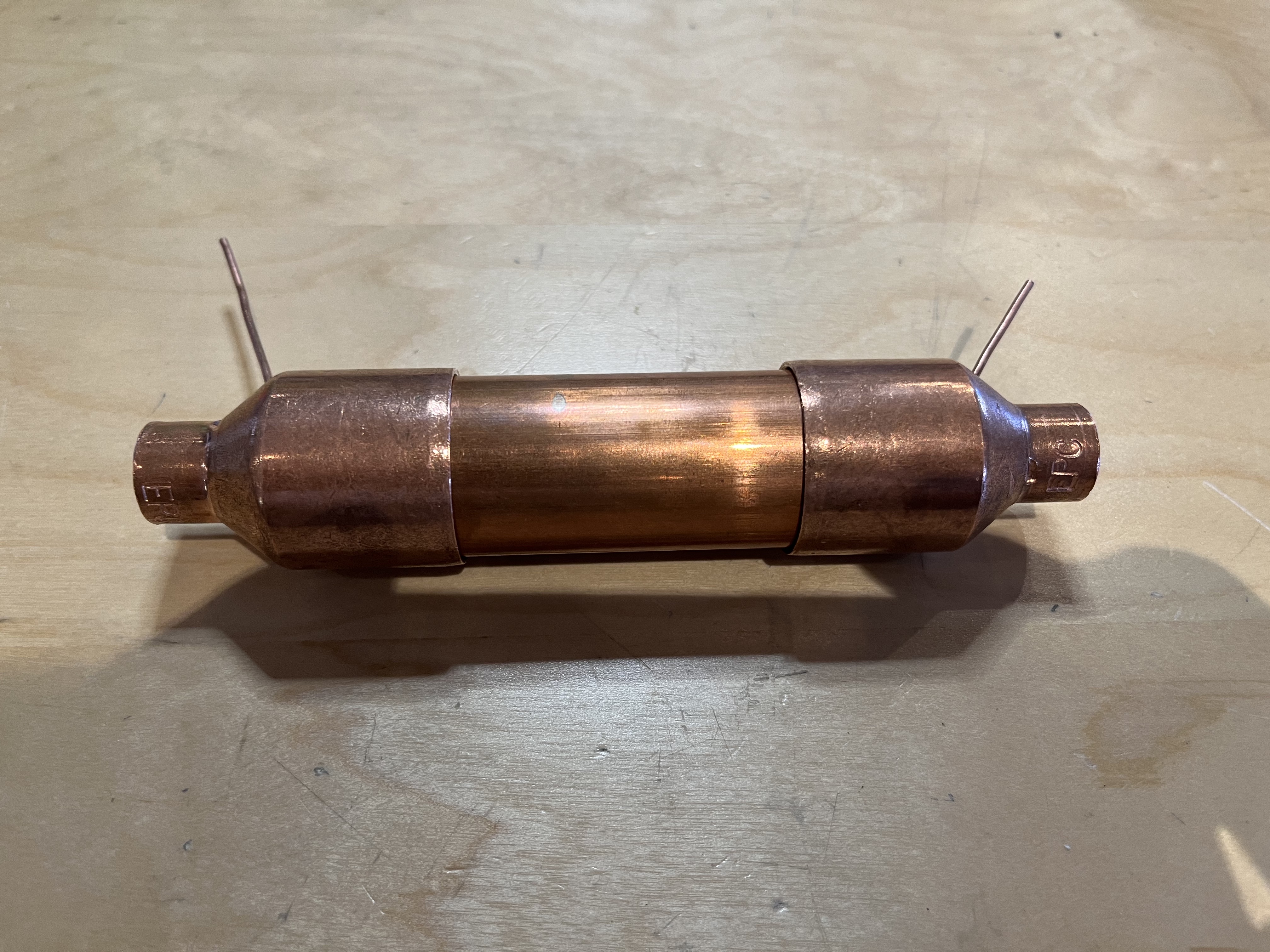
The next technology I worked on was a recuperator. A recuperator is a device designed ti increase the efficiency of a cooling system by transferring spare cooling capacity from the evaporating working fluid to the high-pressure liquid line. This amplifies the power of the condenser and delivers a cooled liquid refrigerant, which is capable of removing more heat than a warm liquid at the same pressure. This idea has been used in other refrigeration designs, so I thought it prudent to evaluate the effects of a recuperator on our device. I built one from a combination of different copper pipes and soft copper tubing sizes, and we evaluated its efficacy on our modular test device.
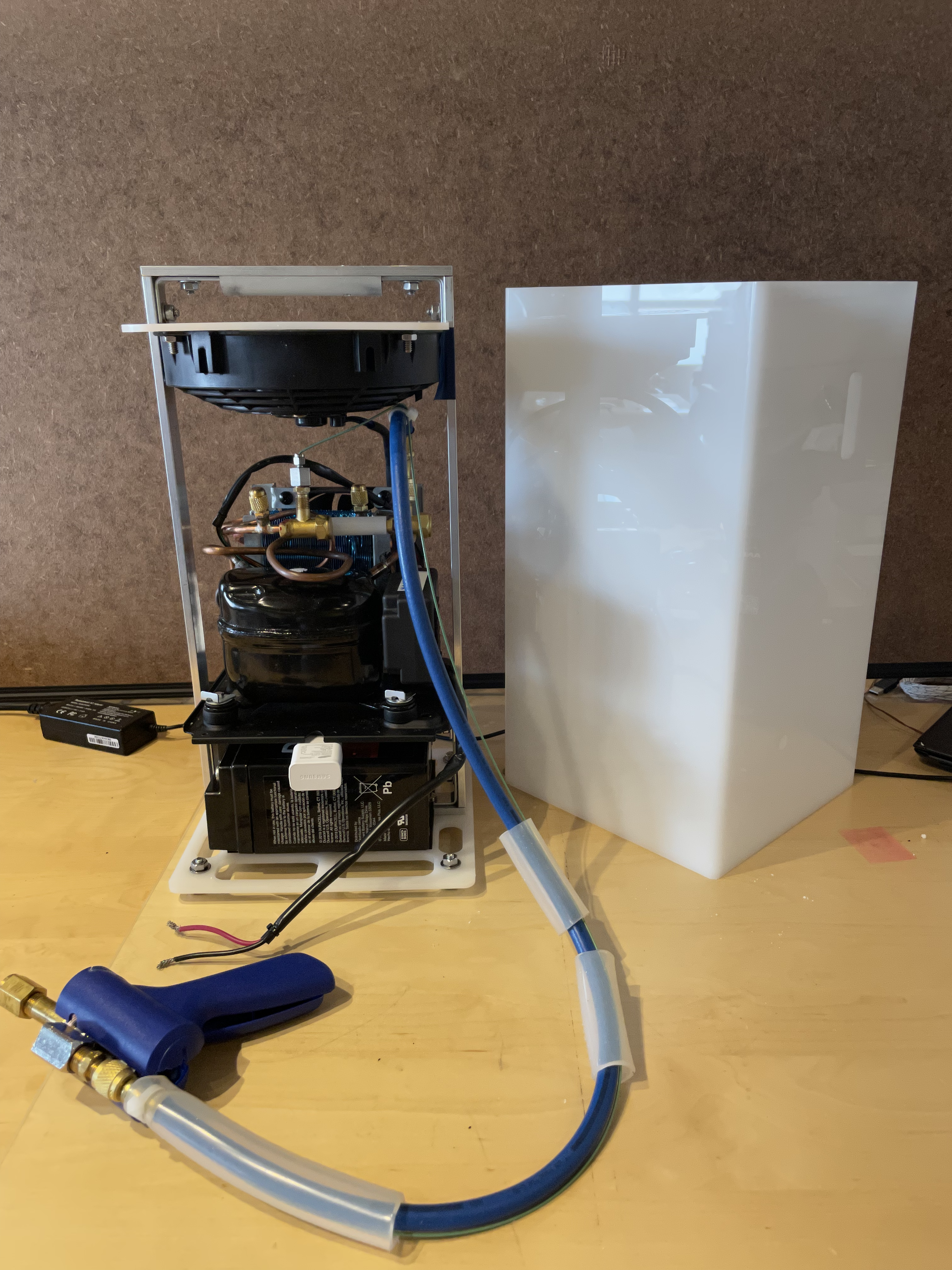
As part of the Y-Combinator class of 2021 showcase, I built a functional prototype of a fully battery-powered "off-grid" capable cryoablation system. The design was intentionally more polished and friendly, taking into consideration the human factors at play in the clinics where it would be used. The device used a 24VDC system to cool a probe tip similar to our pre-existing systems, but was contained in an acrylic case using an aluminum chassis for stability and robustness.